
BLDC Servo Drive Sizing Tool
Estimate steady DC bus current at one operating point. Validate motor phase current and thermal limits separately.
Method & limits
What the estimator calculates
It converts a steady shaft torque-speed point into an approximate DC supply demand. The efficiency input is the combined motor and drive efficiency for that operating point.
Calculation
Pshaft = torque × 2π × RPM ÷ 60
Pdc ≈ Pshaft ÷ ηtotal
Ibus ≈ Pdc ÷ DC bus voltage
ηtotal is the entered efficiency divided by 100. This simplified estimate assumes steady operation and does not model acceleration, regenerative energy, cable losses, or a changing load cycle.
Evidence and interpretation
TI's motor-control guide documents separate board supply voltage and current-sense parameters, alongside motor phase resistance, inductance, and back-EMF data. The exact meanings and limits are drive-specific; consult the selected manufacturer's datasheet.
Texas Instruments: Sensorless FOC Motor Control User GuideTI source checked and page content reviewed on .
Important boundary
DC bus current is not motor phase RMS or peak current. Selecting inverter current ratings requires the motor torque-current relationship or rated phase current, the full motion duty cycle, peak duration, and thermal/derating data. The calculator does not infer those missing values.
Three checks before choosing a drive
A BLDC servo drive must match the motor and application across the full operating envelope. These checks need model-specific data:
- Motor current: Confirm the motor's torque-current data, rated phase current, acceleration torque, and the drive's continuous and time-limited peak-current definitions.
- Thermal duty: Share the torque-speed cycle, peak duration, ambient temperature, enclosure, and cooling path. A single operating point cannot establish continuous thermal capability.
- Voltage and interface: Check bus minimum and maximum, regeneration handling, motor back-EMF at target speed, encoder compatibility, and command protocol against the exact drive model.
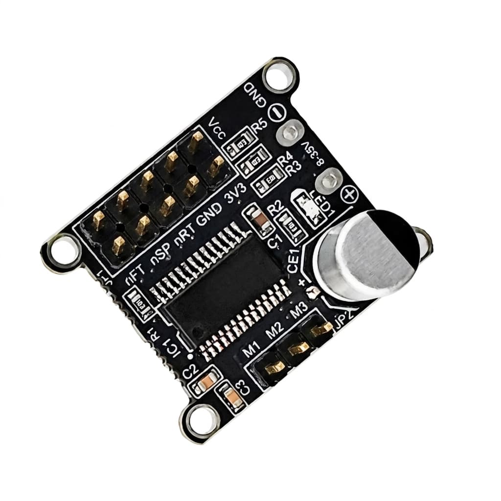
Example micro servo drive board. Current capacity, cooling needs, and continuous ratings depend on the exact model and installation.
Compare the Complete Motion System
A BLDC servo, closed-loop stepper, and AC servo cannot be ranked by generic efficiency or cost percentages. Compare the exact motor-drive package against the same load, speed, duty cycle, and installation conditions.
| Decision dimension | Closed-loop stepper | BLDC servo drive | AC servo system |
|---|---|---|---|
| Load fit | Check the motor torque-speed curve, holding requirement, and encoder correction behavior. | Check motor torque-speed data, phase-current limits, and commutation/feedback support. | Check the matched motor-drive curve and the required continuous and peak duty. |
| Supply and voltage | Verify the drive supply range and bus behavior under load. | Check DC bus minimum/maximum, back-EMF headroom, and regeneration handling. | Verify the site supply, drive input, and braking/regeneration requirements. |
| Feedback and control | Confirm encoder, command interface, and fault feedback. | Confirm encoder/commutation, supported control modes, and fieldbus. | Confirm the motor-drive feedback pair and machine network. |
| Cost and envelope | Compare the quoted motor, drive, feedback, wiring, and cooling package. | Compare the quoted motor, drive, feedback, wiring, and cooling package. | Compare the quoted motor, drive, feedback, wiring, and cooling package. |
If the robot uses a fixed low-voltage DC bus, compare the bus assumptions in our 24V servo drive guide and 48V servo drive guide. Browse the servo drive product range or the engineering resource hub for related selection resources.
Have the motor datasheet and duty cycle?
Request a model-specific drive fit review.Example Closed-Loop Control Architecture
Example signal and feedback path. Confirm protocol, encoder, and control-loop support on the selected drive.
Risks & Design Trade-offs
The main risk is selecting from one operating point or a generic technology comparison instead of exact motor, drive, and application data.
Duty-cycle mismatch
Risk: A steady torque-speed point does not describe repeated acceleration, peak duration, dwell, or cooling intervals.
Mitigation: Provide the complete motion cycle and ambient/cooling conditions. Check the selected manufacturer's continuous, peak, and thermal derating data.
Bus voltage and regeneration
Risk: Motor back-EMF and drive voltage limits can constrain high-speed operation; deceleration can also return energy to the DC bus.
Mitigation: Check motor back-EMF data, bus minimum/maximum, voltage modulation limits, and the drive's regeneration or braking provisions. Do not apply a generic voltage margin.
Feedback and commissioning
Risk: An unsupported encoder, communication profile, or motor parameter set can prevent commissioning even when voltage and current appear suitable.
Mitigation: Confirm encoder interface and resolution, protocol/profile, motor configuration workflow, and fault reporting on the exact drive before approving samples.
Frequently Asked Questions
What current does this estimator calculate?
It estimates average DC bus input current at one steady torque-speed operating point using the entered combined motor-and-drive efficiency. It does not calculate motor phase RMS current or a drive peak-current rating.
What data is needed to size motor phase current?
Use the motor torque-current constant or rated current and torque-speed data, plus the application duty cycle, acceleration, peak duration, cooling conditions, and the drive manufacturer’s phase-current definitions. Confirm the result against the exact drive datasheet and thermal limits.
Can a BLDC servo drive control a PMSM motor?
Some FOC drives support both BLDC and PMSM motors, but compatibility depends on the drive firmware, motor electrical data, commutation or feedback method, voltage range, and current limits. Confirm support for the specific motor and drive combination.
Does moving from 24 V to 48 V halve current?
At the same DC input power, the ideal average DC bus current is inversely proportional to bus voltage. This does not determine motor phase current or guarantee lower winding losses; check the motor, inverter, wiring, bus range, and thermal limits together.
Inquiry Email
Include drawings, torque/speed, protocol, and prototype quantity.