LogoCustom Robot Servo
Start inquiry
LogoCustom Robot Servo
WhatsApp
LogoCustom Robot Servo

China-based custom robot servo OEM supplier for motors, drives, smart servos, actuators, and global delivery.

Inquiry Email

[email protected]

Email app

Include drawings, torque/speed, protocol, and prototype quantity.

Instant Chat

+8618857971991

Chat on WhatsApp

Direct response from our engineering team.

Products
  • Custom Robot Servo
  • Custom Servo Motors
  • Harsh Environment Servo Motors
  • Custom Servo Drives
  • Integrated Robot Servos
  • Robotic Joint Servo Actuators
  • Linear Joint Servo Actuators
  • Smart Servo OEM
Solutions
  • Humanoid Servo Systems
  • Gripper Servo Integration
  • Mobile Robot Servo Platforms
  • Medical Robot Servo Modules
OEM Capabilities
  • 12-Gate Execution Model
  • Drawing to Production
  • Motor Drive Matching
  • Servo PCBA and SMT
  • Assembly and Test
  • RFQ Review
Resources
  • Blog
  • Engineering Hub
  • Engineering Lab
  • About
  • Contact / RFQ
  • Privacy Policy
  • Cookie Policy
  • Terms of Service
© 2026 Custom Robot Servo. All Rights Reserved.|Custom Robot Servo is operated by Linkup Ai Co., Ltd.|Manufacturing coordination through the Linkup Precision advanced manufacturing network.
  1. Home
  2. Products
  3. Linear Joint Servo Actuators

Linear Joint Servo Actuators

Custom linear joint servo actuator programs combining servo motor, screw transmission, guide interface, sensor feedback, brake, housing, and drive matching for robot axes that push, lift, clamp, or extend.

Target Buyer:For teams that need actuator-level axial force and stroke control, not just a rotary motor with a generic screw bolted on later.
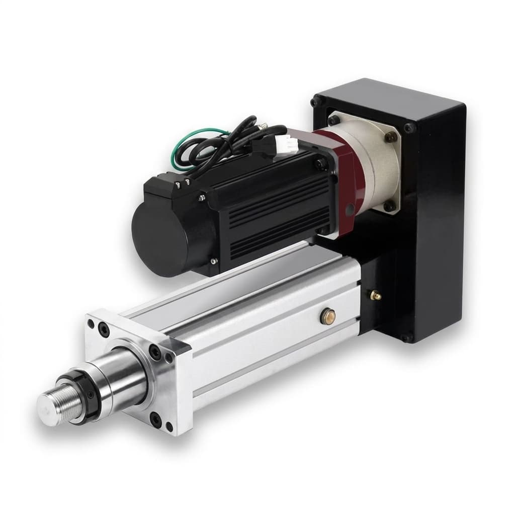
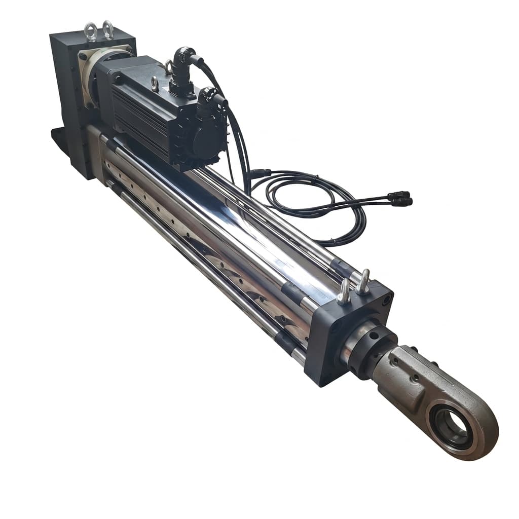
Custom linear joint servo actuator assembly

Capability Highlights

  • Servo motor and screw transmission matching for axial force, stroke, speed, backdrivability, backlash, and thermal hold duty
  • Review paths for ball screw, lead screw, planetary roller screw, belt-assisted, and compact guided linear modules
  • Integrated validation for side-load control, anti-rotation, encoder or linear feedback, brake behavior, noise, and end-of-line force testing

Typical Applications

  • Humanoid leg linear joints and compact knee or ankle assistance axes
  • Robotic gripper push rods, tool changers, clamp axes, and end-effector slides
  • AMR lift columns, sensor mast extension, and battery-powered service mechanisms
  • Medical and lab automation Z axes, syringe or sample handling, and controlled pressing
  • Industrial inspection probes, machine adjustment axes, and compact linear positioning modules

Engineering Focus

  • Translate axial force, stroke, speed, acceleration, duty cycle, and holding time into motor torque, current, screw lead, and thermal load
  • Select screw type, nut preload, guide support, anti-rotation method, lubrication, end stops, and seal strategy as one actuator package
  • Clarify whether position feedback comes from motor encoder, output encoder, linear scale, limit switches, or application-side sensing
  • Plan tests for thrust force, speed, backlash, repeatability, noise, temperature rise, side-load sensitivity, brake hold, and cycle life

Key Evaluation Matrix

MetricTypical RangeWhy It Matters
Axial force and strokeBuyer-defined force, peak force, hold force, stroke, speed, and accelerationLinear joints fail when rotary torque is sized without screw lead, efficiency, holding time, and heat rise considered together.
Transmission choiceLead screw, ball screw, planetary roller screw, belt-assisted, or custom guided moduleThe transmission sets force density, efficiency, noise, backdrivability, cost, lubrication, and cycle-life tradeoffs.
Feedback and retentionMotor encoder, output encoder, linear scale, limit switch, brake, mechanical stopServo stability and safety depend on knowing where the actuator actually is under load and what happens when power is removed.

Selection Logic

SituationRecommended PathEvidence to Confirm
The axis requires controlled thrust rather than rotary outputSize the actuator from axial force, stroke, speed, acceleration, orientation, duty cycle, and holding time before selecting motor or screwForce-speed profile, stroke, vertical/horizontal mounting, hold-force duration, cycle count, current limit, and thermal acceptance limit
The team is choosing between lead screw, ball screw, and roller screwCompare force density, efficiency, backlash, backdrivability, noise, lubrication, cycle life, and unit economics as a system tradeoffLoad case, screw lead, efficiency target, backlash limit, self-locking need, life target, noise limit, and lubrication boundary
The mechanism has side load or alignment uncertaintyDefine guide support, anti-rotation, mounting datum, side-load limit, and assembly inspection before actuator layout releaseCAD section, rail or guide plan, radial load estimate, clevis or flange interface, tolerance stack, and inspection datum

RFQ Checklist

  1. Axial force target, peak force, hold force, stroke, speed, acceleration, duty cycle, and vertical or horizontal orientation
  2. Preferred transmission: ball screw, lead screw, planetary roller screw, belt, or supplier-recommended screw path
  3. Envelope drawing with retracted length, extended length, mounting clevis or flange, guide rail, cable exit, and side-load constraints
  4. Backlash, repeatability, noise, self-locking or backdrivability, brake, end stop, and limit switch requirements
  5. Validation plan for force-speed curve, thermal hold, cycle life, side load, lubrication, and serialized outgoing test data

Risk Controls

  • Axial force is quoted without duty cycle or hold-time data: Calculate current, screw heating, motor temperature, and brake requirement from the full motion profile, not a single peak force.
  • Side load damages the screw or creates stick-slip: Define guide rails, anti-rotation, mounting alignment, radial load limit, and inspection method before actuator layout freeze.
  • A self-locking requirement conflicts with speed or efficiency: Compare lead screw, brake, reducer, and control options using force, speed, efficiency, noise, and backdrivability evidence.

Quote Basis and Commercial Availability

Price Basis

Quoted after drawings, torque-speed targets, electronics scope, validation requirements, and annual volume assumptions are reviewed.

Validity Window

Quote validity, lead time, and sample schedule are confirmed on each proposal after material availability and capacity checks.

Purchasing Route

Start with an RFQ package; commercial terms follow engineering review, prototype scope, pilot-lot gates, and production readiness evidence.

Validation and QC Flow

CheckpointMethodPass Evidence
Force-speed sizing checkMap axial force, stroke, speed, acceleration, screw lead, efficiency, motor current, and drive limit into one operating windowSizing matrix with motor torque, current, screw choice, thermal hold margin, and expected speed under load
Mechanical guidance and backlash checkMeasure backlash, repeatability, side-load sensitivity, anti-rotation behavior, end-stop contact, and mounting alignmentInspection and motion test record showing backlash or repeatability limit, guide alignment, and accepted mounting datum
Hold-force and cycle validationTest brake or self-locking behavior, hold current, temperature rise, noise, lubrication condition, and repeated stroke cyclesSerialized actuator report with force-speed data, thermal log, cycle count, brake status, and post-test inspection notes

Supplier Evidence

Engineering Evidence Pack for Linear Joint Servo Actuators

For product selection pages, the first engineering review should turn the RFQ into testable assumptions, not just a price request.

Scope baseline

Motor, drive, actuator, firmware, harness, fixture, and test responsibility are separated before quotation.

Missing-input list

Open items such as torque-speed data, duty cycle, envelope, protocol, encoder, and target launch country are flagged early.

Sample validation plan

Prototype checks are tied to load profile, thermal rise, backlash, noise, current limit, and end-of-line pass criteria.

Quote assumptions

Tooling, fixture, pilot lot, annual forecast, packaging, documentation, and delivery assumptions are made explicit.

Evidence GroupWhat to AttachBuyer Value
Motion and thermalTorque-speed target, current limit, duty cycle, temperature path, and derating assumption.Separates continuous-duty capability from peak torque claims before sample approval.
Interface controlSTEP or drawing revision, flange, bore, cable exit, connector, encoder, and protocol map.Keeps motor, drive, harness, and firmware assumptions aligned before tooling.
Validation recordEVT, DVT, PVT gate criteria, EOL checklist, burn-in profile, and serial or lot traceability.Gives engineering and procurement a common pass/fail basis for pilot lots.
Commercial pathPrototype quantity, pilot build target, annual forecast, delivery country, and packing notes.Improves quote precision and avoids late shipping or documentation surprises.

Download RFQ and Validation Templates

Use these templates before sending a Linear Joint Servo Actuators inquiry so torque-speed data, drawings, thermal assumptions, and sample acceptance evidence arrive in one package.

CSV

Servo RFQ Baseline Checklist

A field-by-field checklist for torque-speed-duty targets, drawings, protocol, sample quantity, acceptance tests, and open decisions.

Use before the first supplier email so engineering, sourcing, and procurement are aligned on required inputs.

CSV

CSV

Servo Validation Plan Template

A starting validation matrix for torque, current, heat rise, backlash, encoder zero, communication, burn-in, and outgoing inspection.

Use when samples are being scoped and the buyer needs pass/fail evidence before pilot approval.

CSV

CSV

Thermal Derating Worksheet

A compact worksheet for comparing ambient, housing, winding, duty cycle, current limit, and sealed-joint thermal margin.

Use when peak torque looks acceptable but continuous-duty heat rise is still the main project risk.

CSV

Product Gallery

Linear servo actuator motor and screw transmission interface
Linear servo actuator validation and assembly detail
Integrated robot joint interface for linear actuator programs

Buyer FAQ

Can you build linear actuators for humanoid or robot joints?

We can review compact linear joint actuator programs when the force, stroke, envelope, orientation, duty cycle, feedback, and validation targets are clear.

Which screw type should we use?

The answer depends on force density, speed, efficiency, noise, backlash, backdrivability, lubrication, life target, and cost. Ball screw, lead screw, and planetary roller screw paths can each be reviewed from the RFQ data.

Can the actuator include drive electronics?

Yes. A linear joint program can include motor-drive matching, embedded drive PCBA, feedback, brake control, harness, and calibration when those items are included in scope.

Related Resources

  • Robotic Joint Servo Actuators
  • Custom Servo Drives
  • Integrated Robot Servos
  • Assembly and Test
  • Humanoid Servo Systems
  • Contact / RFQ

Inquiry Email

[email protected]

Email app

Include drawings, torque/speed, protocol, and prototype quantity.

Instant Chat

+8618857971991

Chat on WhatsApp

Direct response from our engineering team.