
Budget every frame
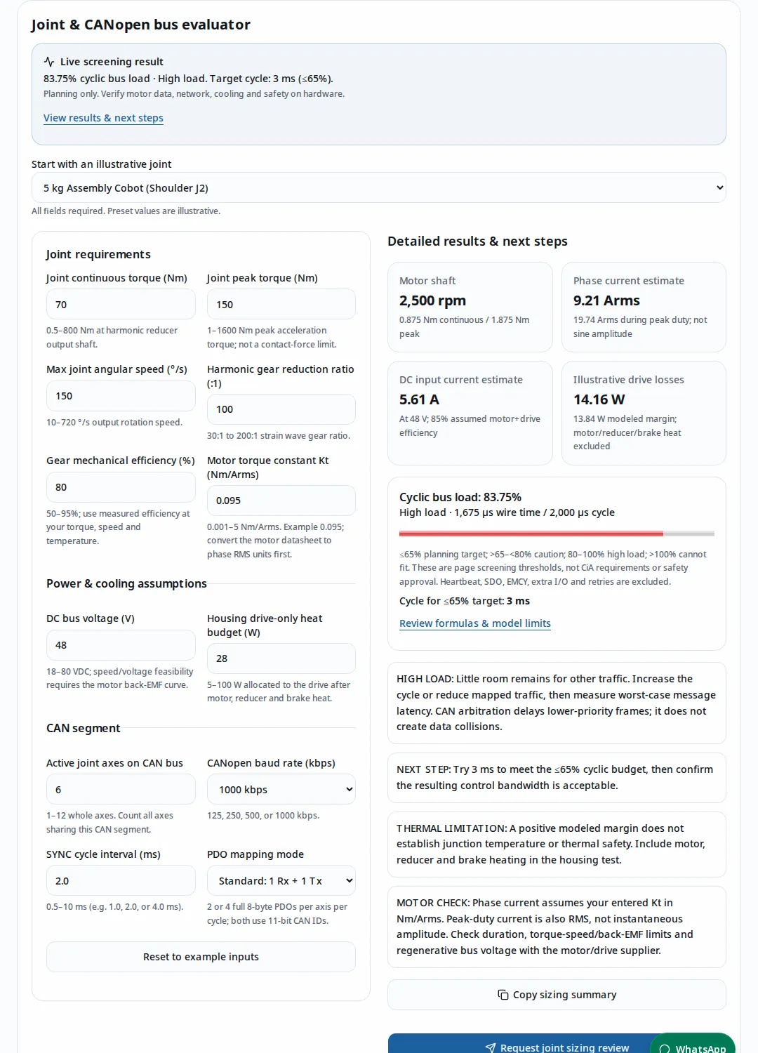
Six axes at 2 ms use 83.75% under this conservative model. A 3 ms cycle meets the page’s ≤65% target; check whether that bandwidth suits the controller.
Calculated scenarios and frame sourcesEstimate motor current, cooling and CANopen bus load. Edit a joint example to begin.
Published by Custom Robot Servo (CRS). Published and reviewed .
Evaluate your joint requirementsLive screening result
83.75% cyclic bus load · High load. Target cycle: 3 ms (≤65%).
Planning only. Verify motor data, network, cooling and safety on hardware.
View results & next stepsAll fields required. Preset values are illustrative.
Motor shaft
2,500 rpm
0.875 Nm continuous / 1.875 Nm peak
Phase current estimate
9.21 Arms
19.74 Arms during peak duty; not sine amplitude
DC input current estimate
5.61 A
At 48 V; 85% assumed motor+drive efficiency
Illustrative drive losses
14.16 W
13.84 W modeled margin; motor/reducer/brake heat excluded
Cyclic bus load: 83.75%
High load · 1,675 µs wire time / 2,000 µs cycle
≤65% planning target; >65–<80% caution; 80–100% high load; >100% cannot fit. These are page screening thresholds, not CiA requirements or safety approval. Heartbeat, SDO, EMCY, extra I/O and retries are excluded.
Cycle for ≤65% target: 3 ms
Review formulas & model limitsHIGH LOAD: Little room remains for other traffic. Increase the cycle or reduce mapped traffic, then measure worst-case message latency. CAN arbitration delays lower-priority frames; it does not create data collisions.
NEXT STEP: Try 3 ms to meet the ≤65% cyclic budget, then confirm the resulting control bandwidth is acceptable.
THERMAL LIMITATION: A positive modeled margin does not establish junction temperature or thermal safety. Include motor, reducer and brake heating in the housing test.
MOTOR CHECK: Phase current assumes your entered Kt in Nm/Arms. Peak-duty current is also RMS, not instantaneous amplitude. Check duration, torque-speed/back-EMF limits and regenerative bus voltage with the motor/drive supplier.
Reviewed . These are engineering screening conclusions, not product ratings.
Six axes at 2 ms use 83.75% under this conservative model. A 3 ms cycle meets the page’s ≤65% target; check whether that bandwidth suits the controller.
Calculated scenarios and frame sourcesUse motor torque and the actual Kt in phase RMS units. Raising DC bus voltage does not by itself halve phase current for the same torque.
Formula and current-reference sourceThe tool’s drive-loss coefficients are illustrative. Shared housing heat, contact resistance and ambient conditions require assembly testing.
Thermal model and limitationsCANopen functionality and a two-channel diagram do not establish a certified safety function. Review the exact safety manual, gravity/brake behavior and cell assessment.
Safety scope and manufacturer guidanceThe evaluator is a deterministic planning model. It assumes motoring operation, steady load, the entered mechanical efficiency, full 8-byte cyclic PDOs on an 11-bit classic CAN segment, and a zero-byte SYNC. Values are computed at full precision and rounded only for display.
| Output | Equation / assumption | What this cannot establish |
|---|---|---|
| Motor speed | n = joint speed (°/s) × gear ratio / 6 | Encoder tracking limits or voltage-speed capability. |
| Motor torque | Tmotor = Tjoint / (ratio × gear efficiency) | Acceleration inertia, friction variation, or reducer peak duration. |
| Phase RMS current | I = Tmotor / Kt; one entered Kt for continuous and peak-duty RMS current | Convert datasheet units first. maxon: current references and torque constants |
| DC input current | Idc ≈ Pshaft / (0.85 × Vbus); 85% is an illustrative combined motor+drive efficiency | Stall/holding copper losses, regeneration, supply transients or measured efficiency. |
| Drive losses | Ploss = 3 × Iphase,rms² × 0.006 ohm + 0.035 × (Pshaft / 0.85) + 3.2 W | Coefficients are unverified placeholders, not device measurements. Positive housing margin is not temperature approval. |
| Cyclic wire time | t = [55 + axes × PDOs per axis × 135] × (1000 / kbps) µs | 135 bits = 132-bit frame budget + 3-bit intermission. Zero-byte SYNC uses 44 + 8 stuffing allowance + 3 bits. Vector: CAN bit stuffing; CiA: classic CAN frame structure and arbitration |
| Planning cycle | U = t / cycle; suggested cycle = ceil[(t / 650) / 0.5] × 0.5 ms | ≤65% is this page’s chosen cyclic traffic target, not a CiA limit. At most 10 ms can be entered in this tool. |
The joint continuous torque and maximum speed are assumed simultaneous for the power/loss illustration. If your trajectory never combines them, use a duty-cycle model instead. Gear efficiency must be checked at the operating point; the 80% default and 0.095 Nm/Arms Kt are examples. This tool cannot infer either from robot payload.
One CAN segment: shared bandwidth across every joint
Electrical bus topology with short stubs; terminate the two physical ends. A long star branch needs a separate physical-layer assessment.
Master / bus end
Set a unique SYNC producer and configure termination.
Base & shoulder
Assign unique node IDs and count mapped command/feedback frames.
Elbow & wrist
Carry the differential pair through joints; keep stubs short.
Last node / bus end
Terminate here; budget gripper and diagnostic traffic too.
Physical-layer basis: TI ISO1042 Rev. F: CAN termination.
| Configuration | Wire time | Cyclic use | Cycle for ≤65% target |
|---|---|---|---|
| 6 axes / 2 PDOs / 2 ms | 1,675 µs | 83.75% | 3 ms |
| 6 axes / 2 PDOs / 3 ms | 1,675 µs | 55.83% | 3 ms |
| 7 axes / 2 PDOs / 2 ms | 1,945 µs | 97.25% | 3 ms |
| 6 axes / 4 PDOs / 2 ms | 3,295 µs | 164.75% | 5.5 ms |
Treat >65–<80% as caution, 80–100% as high load, and >100% as unable to fit under this model. At exactly 100%, no modeled idle window remains. These screening categories do not certify deadlines. Add heartbeat, EMCY, SDO bursts, gripper traffic, errors and device processing before measuring worst-case latency. CAN uses priority arbitration; heavy traffic delays lower-priority messages rather than causing destructive data collisions. CiA: classic CAN frame structure and arbitration
A cycle budget is only the first timing check
Conceptual message flow; local servo loops and sample timing depend on the drive. SYNC cannot eliminate arbitration or controller jitter.
Command PDOs
Schedule setpoints relative to the device’s documented latch event.
SYNC event
Coordinate synchronous behavior using the configured period.
Feedback PDOs
Account for arbitration priority and the drive processing delay.
Remaining window
Reserve heartbeat, faults, diagnostics, retries and timing margin.
The drive profile coordinates state through controlword/statusword exchanges and describes operating functions. Optional support varies, so request the exact EDS, firmware revision, mode list and PDO constraints. The public CiA overview records revised 402-2/-3 parts in 2024; do not assume an older label identifies all supported behavior. CiA: 402 drive and motion control profile
| Decision | Information to obtain | Acceptance evidence |
|---|---|---|
| Position vs torque command | Confirm supported cyclic modes, units, scaling and interpolation behavior. | Master/drive trace showing commanded and actual response. |
| Two vs four PDOs | List bytes in each direction, including status, encoder feedback and feedforward. | Every classic PDO has at most 8 application bytes; additional feedback may need extra frames. CiA: PDO protocol |
| SYNC and local loops | Specify setpoint latch event, feedback age, watchdog and local loop rates. | SYNC coordinates behavior; it does not promise zero jitter. CiA: special function protocols |
| Bit timing | Use the controller’s supported prescaler/segments and full transceiver/cable delay. | A vendor register table is hardware-specific. Beckhoff: CANopen baud rate and bit timing |
For commissioning, verify feedback polarity, torque direction, units and reducer ratio with mechanically supported axes and limited energy. Define communication-loss behavior before testing the full arm. A stopped CANopen state or fault reaction must not be substituted for a validated safety function.
Protocol decision path
Qualitative selection workflow; there are no measured rankings or universal cycle-rate promises.
Payload & deadlines
Write down bytes per axis, sample rate and allowed jitter.
Classic CANopen
Evaluate the tool budget and the actual 8-byte PDO map.
CANopen FD
Check controller, transceiver, stack and master support together.
EtherCAT / split bus
Compare controller changes, harness, validation and total integration cost.
| Option | Reason to consider | Cost / fit risk | Next check |
|---|---|---|---|
| Classic CANopen | Existing compatible master/drives and a cyclic budget with adequate margin. | 8-byte payloads can multiply frame count; slow cycles may miss control needs. | Audit the PDO map and measured schedule. CiA: PDO protocol |
| Multiple CAN segments | Keep existing stacks while distributing joint or tool traffic. | Additional interfaces, wiring and synchronization between segments. | Verify master channel timing and total BOM before choosing. |
| CANopen FD | More data throughput with an appropriate FD-capable system. | Controller, physical layer and stack migration; CiA 1301 behavior must match. | Confirm every node and master supports the intended FD configuration. CiA: CANopen FD |
| EtherCAT / other network | Candidate when the required payload/deadlines cannot fit the CAN design. | Controller/drive/harness changes and commissioning effort need a supplier quote. | Request timing evidence for the actual axis count and payload, then compare total integration cost. |
No universal per-node price or preferred protocol follows from robot payload alone. Compare quoted components, nonrecurring engineering, qualification, harness serviceability and support for the required control loop.
Joint packaging: choose the interfaces before the outline
Conceptual integration sequence; annular and rectangular layouts are both candidates. No dimensions are guaranteed.
Link & reducer
Record output torque, inertia, stiffness and cable travel.
Motor & encoders
Check torque-speed curves, current convention and two feedback interfaces.
Drive & housing
Reserve power devices, thermal contact, connector access and insulation.
Hollow bore
Check harness bend radius, torsion, shielding and assembly clearance.
An annular drive can preserve a central cable route; a rectangular or stacked drive may simplify assembly and service. Compare the complete section drawing, connector mating access, insulation distances and thermal mounting area. No universal bore size follows from a 5 kg or 10 kg payload label.
Specify minimum bend radius and torsion range, shield/ground strategy, stub lengths, strain relief, abrasion protection and the actual cable motion test. A hidden harness can still fatigue or pinch. Distinguish a limited-rotation cable loop from a continuous-rotation slip-ring solution.
Related starting points: collaborative robot wrist drives, 48 V servo drives and BLDC servo drive selection.
Dual feedback: two sensors, separate responsibilities
Conceptual feedback architecture. Extra resolution does not remove compliance or establish a safety function.
Motor encoder
Provide rotor position for commutation and local feedback.
Drive loops
Tune current and velocity behavior with the actual motor.
Reducer & load
Measure friction, hysteresis and torsional compliance.
Output encoder
Observe link position and tune outer feedback without instability.
Motor feedback supports commutation and local motion control; output feedback observes the link side of the reducer. A second encoder can reveal windup that motor feedback misses, but resolution alone does not establish accuracy, bandwidth or safety. Check interface compatibility, sample timing, alignment and fault reporting.
Resonance tuning: measurement before compensation
No frequency-response dataset is available for this page; a numerical Bode curve or phase margin would be unsupported.
Measure plant
Identify response at multiple payloads and joint poses.
Locate modes
Separate structural resonance, encoder errors and cogging.
Tune carefully
Test notch/low-pass settings and gain changes within the drive limits.
Retest envelope
Check tracking, stability and saturation across the operating range.
For a simplified two-inertia torsional model, with output-referred motor inertia Jm·N² and stiffness Ks, f ≈ (1/(2 × pi))·sqrt[Ks·(Jm·N² + JL)/(Jm·N²·JL)], where pi is approximately 3.14159. This conceptual equation omits damping and nonlinear effects; without measured stiffness and inertia, no numerical resonance frequency or notch setting is justified. Ask for frequency-response records across poses and payloads, then verify that filters and gain changes preserve stability and tracking.
STO integration: a separate safety validation path
Conceptual review workflow, not a certified circuit. An ordinary CANopen command or current estimate is not a validated safety channel.
Risk assessment
Determine required safety functions and performance for the cell.
Certified subsystem
Review the exact drive variant, certificate and safety manual.
Stop & hold
Validate stop behavior and support gravity-loaded axes with suitable measures.
Fault validation
Test channels, wiring faults, brake timing and restart interlocks.
This page does not certify a drive or a collaborative application.
STO inhibits drive-generated torque; it does not actively hold a gravity-loaded joint or provide a controlled stop by itself. Determine braking/support and stop sequencing from the selected subsystem’s safety manual and the cell assessment. Kollmorgen’s manual illustrates these distinctions for its own drive; it is not evidence for a Custom Robot Servo product. Kollmorgen: STO and suspended loads
For industrial robot applications, review the applicable edition and scope of ISO 10218-2:2025 — industrial robot applications and ISO/TS 15066:2016 — collaborative robots with the responsible integrator. Public catalogue pages establish document identity/scope, not verified numeric contact limits. This page gives no body-region force table, universal response-time threshold or product PL/SIL claim.
Request the exact part number and firmware, certificate scope, safety manual, required safety performance, channel diagnostics, brake suitability, stop measurements and restart behavior. A torque estimate from phase current does not establish contact force: lever arms, friction, acceleration, tool geometry and trapping conditions all affect the application assessment. Medical and other non-industrial applications need their own applicable framework.
Heat path: component to housing to ambient
Conceptual thermal network. Resistance values and sensor limits require the actual assembly and component datasheets.
Power devices
Estimate conduction and switching loss using phase current.
PCB / interface
Include spreading, contact area, pad thickness and mounting pressure.
Joint casting
Share the heat budget with motor, reducer and brake.
Ambient test
Measure temperatures at worst duty, ambient and joint pose.
| Model output | 24 V bus | 48 V bus | Interpretation |
|---|---|---|---|
| Motor phase current | 9.21 Arms | 9.21 Arms | Same torque and Kt → same modeled phase current. |
| Estimated DC input current | 11.23 A | 5.61 A | Same power/assumed efficiency → half the DC current at twice the voltage. |
| Illustrative drive losses | 14.16 W | 14.16 W | Same result in this simplified model; real switching loss can depend on voltage. |
The comparison does not prove either voltage can reach the requested motor speed. Check back-EMF, modulation reserve, winding resistance/inductance and regeneration. At holding/stall, a power-over-voltage estimate does not capture copper heating; use the supplier’s motor/drive loss model.
For a first thermal-path sketch, temperature rise ≈ Ploss × Rthermal,total, where Rthermal,total is total thermal resistance in K/W. This steady-state approximation is not a junction-temperature guarantee. Obtain actual component resistance curves, interface area/thickness and casting-to-ambient behavior. Include other heat sources and run the intended duty until temperatures stabilize. Sensor indices and derating limits must come from the EDS/manual: manufacturer-specific objects such as 0x2030 are not portable temperature registers. NI: CANopen object dictionary ranges; Beckhoff: drive object 0x60C2.
Illustrative planning exercises calculated with this evaluator; no customer deployment or measured production outcome is claimed.
Premise: Assume six axes, two PDOs per axis, 1000 kbps and a 2 ms cycle.
Calculated result: The model returns 83.75% cyclic utilization. Change the interval to 3 ms: 55.83%.
Next check: Confirm that a 3 ms setpoint rate meets tracking requirements, then test asynchronous bursts and watchdog behavior.
Premise: Assume seven axes with the same two-PDO mapping and a 2 ms cycle.
Calculated result: Cyclic use reaches 97.25%. The ≤65% target needs 3 ms before extra I/O.
Next check: Compare slower scheduling against splitting the tool/axes onto another segment. Validate synchronization and added interface cost.
Premise: Assume six axes, four full PDOs per axis and a 2 ms cycle.
Calculated result: Cyclic use reaches 164.75%; frames cannot fit. The planning target needs 5.5 ms.
Next check: Reduce mapped bytes/frame count only if required feedback remains available; otherwise evaluate another segment or protocol.
| Risk | Consequence | Mitigation / alternative |
|---|---|---|
| Treating presets as payload ratings | Wrong phase current, reducer or drive size. | Use pose/duty load cases and supplier torque-speed curves. If unknown, submit the motor and mechanical model for review. |
| Treating a low bus percentage as a deadline guarantee | Late feedback or communication faults during diagnostic traffic. | Measure schedule and response latency with all nodes, faults and retries; consider a split segment. |
| Using estimated current as a contact-safety limit | Application contact behavior remains unvalidated. | Use the required safety architecture and application tests; request exact safety documents. |
| Optimizing the PCB outline before service/cooling | Rework, harness damage or thermal derating. | Review the complete joint section and duty test before freezing the envelope. |
| Comparing only transceiver prices | Unbudgeted master, software, harness and validation effort. | Quote total BOM, engineering, qualification, spares and lifecycle support for each network option. |
| Demanding more feedback without revisiting bandwidth | Four-PDO mappings cannot fit the original cycle. | Specify the required feedback age first; reduce noncritical traffic or evaluate a different network. |
| Evidence | Available here | Minimum follow-up |
|---|---|---|
| CANopen behavior | Primary protocol summaries and reproducible cyclic calculations. | EDS, PDO map, firmware-specific modes and conformance/interoperability evidence. |
| Motor current / speed | Declared formulas and editable illustrative Kt/efficiency. | Motor curves, unit conversion, measured current and peak duration. |
| Thermal capacity | Illustrative loss calculation; no assembled-joint measurements. | Worst-case duty/ambient temperature log with calibrated sensors. |
| Safety certification | No product-specific certificate or safety validation supplied. | Exact variant certificate and safety manual plus cell validation. |
| Accuracy / resonance | Conceptual dual-loop and tuning workflow; no response dataset. | Measured frequency response, tuning record and tracking results. |
| Production cases / pricing | Worked examples only; no customer records or binding quote. | Authorized project evidence and an application-specific quotation. |
Links reviewed on . Public protocol and manufacturer documentation support the scoped explanations below. ISO links are catalogue/scope records; the full paid normative clauses were not verified. Model coefficients, thresholds and examples are this page’s declared assumptions. No cited manufacturer document certifies our products.
| Primary source | What it supports |
|---|---|
| CiA: classic CAN frame structure and arbitration | Frame fields, intermission, priority arbitration and error handling. |
| Vector: CAN bit stuffing | Theoretical 132-bit full base frame before intermission; basis for this page’s conservative budget. |
| CiA: PDO protocol | 8-byte classic PDO payload, mappings and synchronous transmission. |
| CiA: special function protocols | Classic SYNC with default zero-byte payload; optional counter; EMCY purpose. |
| CiA: 402 drive and motion control profile | Control/status state machine, optional functions and revised 2024 profile parts. |
| CiA: CANopen FD | CAN FD lower layers, CiA 1301 and protocol/stack differences. |
| Beckhoff: CANopen baud rate and bit timing | A vendor-specific example: 75% sample point at 1000 kbit/s; not universal register values. |
| NI: CANopen object dictionary ranges | Manufacturer-specific object range 0x2000–0x5FFF. |
| Beckhoff: drive object 0x60C2 | 0x60C2 is the interpolation time period, not temperature telemetry. |
| TI ISO1042 Rev. F: CAN termination | SLLSF09F, August 2026, sections 8.2.2.1–8.2.2.2 (pp. 25–26): short stubs and termination at both bus ends. |
| maxon: current references and torque constants | Torque-constant/current conventions differ between block and sinusoidal commutation. |
| Kollmorgen: STO and suspended loads | Example manufacturer safety manual: torque inhibition, gravity hazards and controlled-stop limitations. |
| ISO 10218-2:2025 — industrial robot applications | Publication identity and application/cell integration scope; not a product certificate. |
| ISO/TS 15066:2016 — collaborative robots | Public scope/catalogue record only; full normative limits were not verified here. |
Not automatically. The full-frame budget here is 1,675 µs per cycle for six axes with one RxPDO and one TxPDO each at 1 Mbit/s: 83.75% at 2 ms, before other traffic. A 3 ms cycle reduces modeled cyclic use to 55.83%. Confirm the control bandwidth and actual worst-case latency. Vector: CAN bit stuffing
No. In this tool, extended means four PDOs per axis per cycle instead of two. Both settings assume 11-bit identifiers and full 8-byte payloads. A network using 29-bit identifiers needs a different frame budget. CiA: classic CAN frame structure and arbitration
No. It coordinates synchronous behavior. Controller scheduling, arbitration, oscillator behavior and device processing still need to be measured. A SYNC event is not a guarantee that every local servo loop runs on the same edge. CiA: special function protocols
No. Prescaler, segment ranges, oscillator tolerance and propagation delays depend on the controller and transceiver. Beckhoff documents 75% sampling at 1 Mbit/s for its example devices. Use the selected hardware manual and verify the full harness. Beckhoff: CANopen baud rate and bit timing
Only after checking the whole system. CANopen FD needs an FD-capable controller, suitable physical layer, compatible stack and master configuration. Requalify the harness and every participating node; mechanical reuse alone does not establish protocol compatibility. CiA: CANopen FD
No. Link lengths, link masses, pose, acceleration, friction and duty affect demand. The 3 kg, 5 kg and 10 kg presets are illustrative input sets. Replace them with your load-case analysis before choosing a drive.
Current follows torque divided by Kt using a consistent current reference. A datasheet may quote block current or sinusoidal amplitude instead of RMS. Convert its convention before entering Kt; peak-duty output here is also RMS, not instantaneous sine amplitude. maxon: current references and torque constants
For the same motor, torque and Kt, the modeled phase current stays the same. DC input current at a given input power decreases as bus voltage rises. That does not establish inverter heat savings or prove speed capability.
They can observe different sides of the reducer, helping tune tracking. Physical compliance, friction and hysteresis remain. Measure the plant at several poses and payloads before closing an outer position loop or adding notch filters.
No. It does not model contact geometry, stopping distance, force, pressure or application safety performance. An industrial collaborative cell needs an application-specific assessment and validation using applicable standards. ISO/TS 15066:2016 — collaborative robots
No. Removing motor torque can allow a suspended load to move. Determine appropriate braking or mechanical support, stopping behavior and restart interlocks from the exact safety manual and cell assessment. Kollmorgen: STO and suspended loads
Do not assume so. The safety architecture, sensors, communications and diagnostics must support the required function and validation. Request the exact variant’s certificate, safety manual and test evidence rather than inferring certification from CiA 402 support. CiA: 402 drive and motion control profile
No product-specific certificate, measurement dataset or customer deployment record is provided with this page. The examples are calculations, not observed production outcomes. Request evidence for the proposed motor, drive and firmware configuration.
Only that the illustrative drive-loss model is below your entered drive-only heat budget. It does not predict junction temperature or include motor, brake and reducer heat. Validate the assembled joint at worst-case ambient and duty.
The configuration cannot meet this tool’s 65% cyclic budget inside its input range. Reduce mapped traffic, distribute axes across CAN segments, or evaluate another protocol. Do not slow the robot control loop without checking its performance requirements.
Read the actual EDS and firmware manual. 0x2030 is in a manufacturer-specific range and is not a universal temperature object; 0x60C2 is not a temperature-monitoring register. Ask the supplier to identify sensor units, update timing and derating behavior. Beckhoff: drive object 0x60C2
Include torque-speed duty, reducer ratio/efficiency, motor Kt and back-EMF data, bus voltage including regeneration, CAN PDO map and deadlines, encoder interfaces, CAD/bore envelope, cooling conditions, required safety functions and quantities. Copy the sizing summary with assumptions and attach it to your inquiry.
The tool shows a selectable text summary if clipboard access fails. You can copy it manually or contact engineering with the motor datasheet and the parameters you already know.
Copy the evaluator summary and include your motor datasheet, torque-speed duty, reducer data, PDO map, CAD envelope, cooling conditions, required safety functions and quantities. If inputs are unknown, send what you have so the missing evidence can be identified before sizing.
Open the RFQ contact form or use an inquiry channel below.
Inquiry Email
Include drawings, torque/speed, protocol, and prototype quantity.