
Geometry before axis labels
Use actual perpendicular CoG distance and CAD inertia. A long centered J6 tool need not have a large gravity moment.
Review method and limitsWrist drive screening · J4 / J5 / J6
Enter tool geometry and CANopen timing to screen torque, current, heat budget and bus load. Use the report below to plan prototype tests.
Published · Reviewed · By Custom Robot Servo (CRS). Illustrative model; hardware performance unverified.
Request wrist drive RFQIllustrative examples, not product ratings. Change inputs to match your CAD mass properties; every field is required.
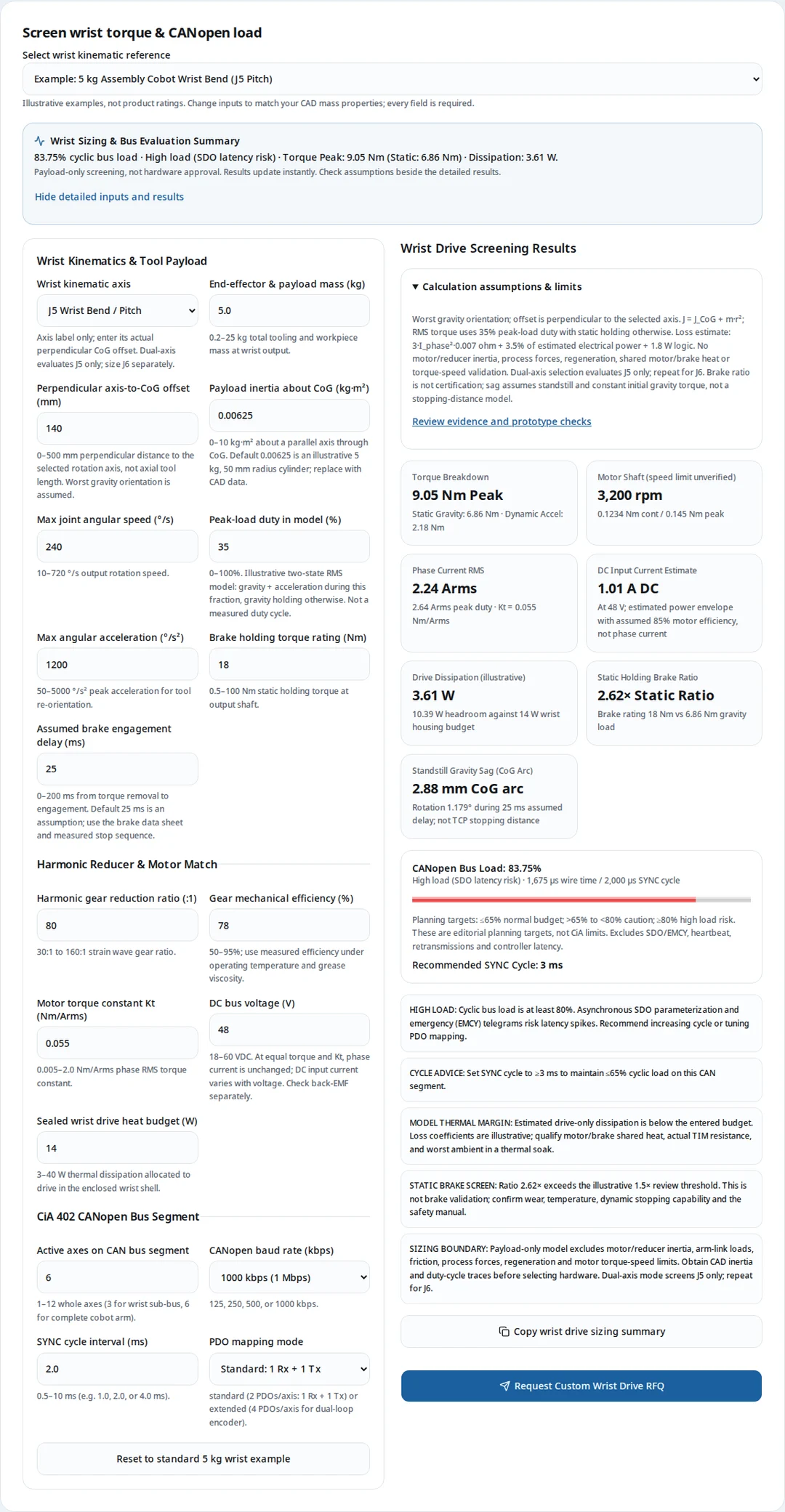
Wrist Sizing & Bus Evaluation Summary
83.75% cyclic bus load · High load (SDO latency risk) · Torque Peak: 9.05 Nm (Static: 6.86 Nm) · Dissipation: 3.61 W.
Payload-only screening, not hardware approval. Results update instantly. Check assumptions beside the detailed results.
Use actual perpendicular CoG distance and CAD inertia. A long centered J6 tool need not have a large gravity moment.
Review method and limitsAt fixed torque and Kt, 24 V and 48 V need the same phase current. Lower DC current is a separate harness benefit.
Review method and limitsThree axes use an illustrative 865 µs per cycle; six use 1675 µs. A shared board does not automatically reduce the PDO count.
Review method and limitsStatic brake ratio, loss margin and bus occupancy identify review work. They do not establish a safety rating, contact limit or measured stop.
Review method and limitsMeasure r perpendicular to the selected axis; alpha is angular acceleration. Axial tool length does not determine roll-axis gravity torque; use J = J_CoG + m·r².
First-principles screening uses Tg = m·g·r at the worst gravity orientation, J = J_CoG + m·r², and Tpeak = Tg + J·alpha, where alpha is joint angular acceleration in rad/s². The RMS estimate is √[d·Tpeak² + (1−d)·Tg²], where d is the entered peak-load duty. This two-state model includes holding torque and excludes link, motor and reducer inertia, friction and process loads. Replace it with a complete trajectory model for selection.
| Axis | Required measurement | Common misuse | Next check |
|---|---|---|---|
| J4 roll | Perpendicular CoG distance about forearm rotation axis | Using full axial tool length as a radial lever | Include all downstream links in the final model |
| J5 pitch | Distance from bend axis to combined tool/workpiece CoG | Entering TCP reach without mass properties | Evaluate worst orientation and acceleration |
| J6 flange roll | Radial eccentricity and spin-axis CoG inertia | Inferring eccentricity from axis name | Add screwdriving reaction and torque-speed limits |
| Dual J5+J6 | Run one calculation per axis | Treating one board as one motion axis | Combine thermal loads and count physical axes on bus |
Illustrative upstream inertia addition: 0.05 kg at 1.3 m perpendicular reach adds 0.0845 kg·m². Actual reach and pose determine this value; no universal payload loss percentage follows.
Annular boards preserve a cable path; shared boards can reduce connectors but couple heat and service replacement. Neither layout guarantees a weight or cost saving.
| Option | Potential benefit | Cost or integration risk | Evidence to request |
|---|---|---|---|
| Annular custom board | Central routing path for cables or tubing | NRE, thermal-spreader fit and assembly access | Board/connector CAD, keep-outs and thermal contact drawing |
| Shared dual-axis board | Fewer duplicated connectors or logic components | Shared heat, common faults and whole-module replacement | Two-axis loss map, EDS, simultaneous operation trace |
| Separate standard drives | Independent replacement and smaller prototype commitment | More harness space and connectors | Fit check, complete BOM and service procedure |
Dimensions, weight savings and pricing are unknown until a specific design and quote exist. Compare NRE amortized over expected quantity, unit cost, harness labor, fixture cost and spare-module policy. A slip ring or validated flex harness may be needed for the required J6 rotation range.
Raising 24 V to 48 V halves estimated DC input current at equal power. Phase current and its I²R loss remain unchanged at equal torque and Kt; switching losses need a device-specific model.
For an identified heat path, temperature rise = power × thermal resistance. Unknown resistance, contact area and shared heat prevent a shell-temperature prediction from drive loss alone.
Motor current is Tmotor/Kt with a consistent phase-RMS convention. The model estimates electrical power using 85% assumed motor efficiency, then IDC = Pelec/Vbus. These are screening envelopes, not measured averages. Current definitions must be checked against maxon: Torque constants and commutation current references.
| Parameter | 24 V | 48 V | Meaning / limitation |
|---|---|---|---|
| Phase RMS current | 2.24 Arms | 2.24 Arms | Unchanged at fixed torque and Kt |
| Estimated DC input current | 2.03 A | 1.01 A | Halves at equal estimated electrical power |
| Illustrative drive-only loss | 3.61 W | 3.61 W | Same coefficients; actual switching loss may vary with voltage |
| Shell temperature / cable gauge | Unknown | Unknown | Requires thermal-path and conductor-rating data; no automatic safe temperature or wire size |
Loss model: 3·Iphase²·0.007 ohm + 0.035·Pelec + 1.8 W. These coefficients are illustrative. For an identified path temperature rise = power × thermal resistance, but junction-to-case and case-to-ambient resistances refer to different temperatures. Include motor/brake heat, TIM area and compression, ambient, mounting and component limits in a physical soak. A positive drive-only budget is not a touch-temperature approval.
At 1 Mbps, three axes with one Rx and one Tx PDO each use 55 + 6×135 = 865 µs. At 2 ms that is 43.25% cyclic occupancy, excluding other traffic.
The 11-bit classic CAN planning allowances are 135 bits per full 8-byte PDO (108 unstuffed + up to 24 stuff bits + 3 intermission) and 55 bits for a zero-byte SYNC (44 + up to 8 + 3). These derived envelopes follow frame structure and stuffing rules; not every payload produces maximum stuffing. Sources: CiA: Classic CAN frame format, Vector: CAN bit stuffing, CiA: PDO protocol and CiA: SYNC and EMCY protocols.
| Topology / mapping | Wire time | Load at 1 ms | Load at 2 ms | Rounded cycle for ≤65% |
|---|---|---|---|---|
| 2 axes, standard | 595 µs | 59.50% | 29.75% | 1.0 ms |
| 3 axes, standard | 865 µs | 86.50% | 43.25% | 1.5 ms |
| 6 axes, standard | 1675 µs | 167.50% — over capacity | 83.75% — high load | 3.0 ms |
| 3 axes, extended (2 Rx + 2 Tx each) | 1675 µs | 167.50% — over capacity | 83.75% — high load | 3.0 ms |
Recommended cycle = ceil[(wire time / 0.65) / 0.5 ms]·0.5 ms, with a 0.5 ms minimum. The 65% target and 80% warning threshold are editorial planning choices, not CiA compliance limits. Excludes heartbeat, SDO/EMCY, error frames, retransmission and controller latency. A zero-byte SYNC is assumed; counter-enabled SYNC requires a revised budget.
Register values, sample point and achievable deadlines depend on the controller clock, transceiver and harness. Obtain the actual EDS/PDO map and measure worst-case message age under full traffic. If cycles cannot meet the control deadline, compare a dedicated wrist segment, local interpolation or a supported higher-bandwidth interface. CiA: 402 drive profile defines profile behavior, not a universal interpolation algorithm or latency guarantee.
An output encoder observes deflection after the reducer. Compensation requires tuning and cannot remove physical compliance or guarantee stability.
No measured frequency response is available here. Resonance frequency, attenuation and phase effects must be identified on the assembled mechanism.
| Option | What it observes | Limitation / cost | Validation |
|---|---|---|---|
| Motor feedback only | Rotor motion before reducer | Cannot directly observe output deflection | Tool tracking across load and temperature |
| Motor + output encoder | Rotor and flange pose | Extra sensor, wiring and tuning; compliance remains | Stability margins and loaded tracking |
| Notch / feedforward | Response at identified disturbance or resonance | May alter phase or fail after tool changes | Measured frequency response and retest across tools |
No measured Bode plot, notch attenuation, cogging reduction or guaranteed loop frequency is available for this page. Request logs for the proposed firmware and mechanism; identify tool-dependent resonances rather than prescribing a universal 58 Hz notch.
A joint-current estimate cannot establish collaborative contact safety. Determine application limits from the applicable standards and validate the complete robot cell.
The applicable robot-cell and collaborative-system scopes are described by ISO 10218-2:2025 — Robot application integration and ISO/TS 15066:2016 — Collaborative robots. Their public summaries do not establish the numeric limits for your application. This page supplies no body-region force table, pressure threshold, universal touch temperature or contact-energy allowance.
The integrator must assess body region, transient versus constrained contact, contact area, speed, tool edges and trapping. Validate the required force and pressure behavior on the complete cell using the applicable documents and test plan. Motor current and an ordinary software torque limit alone do not establish a safety function.
This model excludes initial speed, motor/reducer inertia and brake torque buildup. Angle is in radians; CoG arc displacement is not TCP drop or a measured stopping distance.
| Check | Model | Missing evidence | Action |
|---|---|---|---|
| Static holding ratio | Output-equivalent brake torque / worst-pose gravity torque | Mounting shaft, temperature, wear and dynamic capability | Obtain brake rating and agreed static margin |
| Standstill sag | angle ≈ ½(Tg/J)·delay²; CoG arc ≈ r·angle | Initial speed, full inertia, nonlinear gravity and torque buildup | Use full stop model and measured maximum drop |
| PWM hold / flyback clamp | Not simulated | Coil data, approved clamp stress and engagement response | Use brake supplier-approved circuit and sequence |
The 25 ms delay is an editable assumption; 1.5× is an illustrative static review threshold. Neither is a safety requirement or brake qualification. If the approximation exceeds 5° rotation, a warning directs you to a more complete model. STO removes active torque and cannot support a suspended load: Kollmorgen: STO and suspended loads.
Ordinary CiA 402 support does not establish STO, PL or SIL. Obtain the applicable certificate, timing data and brake instructions for the exact hardware and firmware.
| Item | Evidence needed | Current status |
|---|---|---|
| Required and achieved PL / SIL | Application risk assessment, exact-variant certificate and validation | Unknown; no CRS certificate disclosed |
| STO / SS1 / brake behavior | Safety manual, response-time limits, wiring and tested sequence | Unknown; no universal <10 ms requirement asserted |
| Diagnostic coverage and reliability | Safety analysis, component assumptions and mission profile | Unknown; no MTTFd or DCavg value disclosed |
See the scope of ISO 13849-1:2023 — Safety-related control systems. Ordinary CiA 402 support and a dual-channel block diagram do not prove a performance level. Select the required functions and obtain the applicable safety manual before integration.
All values below use the same engine as the tool. Unless stated, inputs use the 5 kg default, 140 mm radial offset, 0.00625 kg·m² CoG inertia, 35% peak duty, 25 ms brake delay, 80:1 reduction, 78% efficiency, Kt 0.055 Nm/Arms, 48 V, six axes at 1 Mbps, standard PDOs and 2 ms SYNC. These are software examples, not customer deployments.
Default inputs; 14 W drive-only heat budget.
Peak 9.05 Nm · Phase RMS 2.24 Arms · Loss 3.61 W · Thermal headroom 10.39 W · Bus 83.75% · Standstill CoG arc 2.88 mm.
The six-axis bus is high-load at 83.75%; use at least 3 ms for the 65% target or reconsider the segment. Positive modeled heat margin still needs a soak test.
10 kg, 200 mm radial offset, 0.0125 kg·m² CoG inertia, 100:1 reduction, 1500°/s² acceleration; other inputs unchanged.
Peak 30.41 Nm · Phase RMS 5.58 Arms · Loss 7.75 W · Thermal headroom 6.25 W · Bus 83.75% · Standstill CoG arc 2.97 mm.
The entered 18 Nm brake is below the 19.61 Nm static load. The illustrative 1.5× screen would require 29.42 Nm output-equivalent; validate actual stopping and brake conditions.
2 kg, 17.5 mm radial offset, 0.0025 kg·m² CoG inertia, 720°/s, 2500°/s², 50:1 reduction; other inputs unchanged.
Peak 0.48 Nm · Phase RMS 0.18 Arms · Loss 2.06 W · Thermal headroom 11.94 W · Bus 83.75% · Standstill CoG arc 0.60 mm.
Required motor speed is 6000.00 rpm. Check the actual torque-speed curve at the chosen bus voltage and reducer input limit; this tool cannot confirm speed feasibility.
Default mechanics, 24 V and 10 W drive-only budget; other inputs unchanged.
Peak 9.05 Nm · Phase RMS 2.24 Arms · Loss 3.61 W · Thermal headroom 6.39 W · Bus 83.75% · Standstill CoG arc 2.88 mm.
Phase current and modeled loss match the 48 V example. DC input current doubles; the smaller entered budget changes thermal headroom. Review voltage headroom and thermal path separately.
| Risk | Consequence | Mitigation | Alternative |
|---|---|---|---|
| Wrong geometry or current convention | Under-sized motor, drive or brake | CAD properties and consistent Kt/phase-RMS units | Send CAD and duty trace for engineering review |
| Positive heat margin mistaken for safe shell temperature | Overheated wrist or unacceptable surface contact | Shared-source thermal soak and application temperature criteria | Larger conduction area, lower duty or external drive location |
| Custom PCB too early | NRE and fixture cost dominate a small batch | Compare total cost at agreed production volume | Prototype with standard separate boards |
| Fast coordination on overloaded classic CAN | Missed update deadline despite correct PDO values | Trace full traffic; six standard axes need 3 ms for this target | Dedicated segment or supported faster transport |
| Fixed notch or brake settings copied to a new tool | Instability or excessive drop after tool change | Retest response and stop sequence for each load case | Lower speed/acceleration pending qualification |
| Scope | Known / assumed | Unknown / next evidence |
|---|---|---|
| Payload mechanics | First-principles equations with entered radial geometry and two-state duty | Whole-arm dynamics, process forces and measured torque |
| Bus occupancy | Declared frame allowances and PDO count; deterministic software arithmetic | Actual EDS mapping, latency, jitter and fault recovery trace |
| Thermal estimate | Illustrative loss coefficients; user-entered heat budget | Vendor loss curves, shared heat, ambient and steady-state temperatures |
| Brake sag | Entered delay; standstill constant-torque approximation | Full stopping motion, brake wear and measured engagement/drop |
| Physical performance / certification | No laboratory record or CRS safety certificate supplied for this page | Exact-variant test records, safety manual and independent validation |
Primary sources checked 22 October 2026. Public standards landing pages establish title, edition and scope only. Obtain applicable full documents and variant-specific manuals for design and validation; these links are not evidence of CRS certification.
| Source | Supported scope / limitation |
|---|---|
| CiA: Classic CAN frame format | 11-bit base frames, 3-bit intermission, arbitration and error retransmission. Frame allowances below are our derived planning model. |
| Vector: CAN bit stuffing | Stuff-bit insertion rule; not a guarantee of application latency. |
| CiA: PDO protocol | Classic CANopen PDO payload up to 8 bytes; mapping and synchronous transmission. |
| CiA: SYNC and EMCY protocols | Default zero-byte SYNC and optional counter. This tool assumes no counter. |
| CiA: 402 drive profile | Drive state machine and process data. Support for individual modes and objects must be checked in the EDS and firmware. |
| maxon: Torque constants and commutation current references | Current conventions differ. Convert the motor torque constant to the phase-RMS convention required by this tool. |
| Kollmorgen: STO and suspended loads | Manufacturer example: STO removes active motor torque; suspended loads need mechanical support. This is not evidence for CRS hardware. |
| ISO 10218-2:2025 — Robot application integration | Published scope for industrial robot applications and cells, not a source for payload-specific torque equations. |
| ISO/TS 15066:2016 — Collaborative robots | Collaborative system and work-environment scope. Public summary does not verify numeric force, pressure or touch-temperature limits. |
| ISO 13849-1:2023 — Safety-related control systems | Correct 2023 edition landing page. Required PL and achieved PL depend on the safety function and validation. |
Wrist packaging, distal mass and tool inertia can constrain the design even when torque is modest. Extra mass adds inertia about an upstream axis according to its perpendicular distance squared; there is no universal payload penalty percentage.
Use the perpendicular distance from the selected rotation axis to the combined tool/workpiece CoG. For a centered J6 tool this can be zero despite a long tool. TCP position and CoG position are different quantities.
The parallel-axis model is J = J_CoG + m·r². Obtain J_CoG about a parallel axis from CAD. The default 0.00625 kg·m² represents an illustrative 5 kg, 50 mm radius cylinder; it is not inferred from every payload.
No. The selector labels the J5 screening calculation. Repeat with J6 geometry and count all physical controlled axes on the CAN segment. Sharing a board does not automatically halve PDO traffic.
A central bore can preserve routing for cables or tubing. Confirm connector clearance, bending radius, assembly access and heat-spreader contact against CAD before commissioning a custom PCB.
It may reduce connectors and duplicate logic, but it shares heat and fault exposure. Node IDs, multi-axis object dictionaries and supported PDO maps are firmware-specific; obtain the EDS and test both axes.
Reference: CiA: 402 drive profile
No. Compare NRE, minimum order, validation fixtures, yield, firmware maintenance and replacement cost at the same annual volume. A standard board may be cheaper for prototypes or small batches.
Do not assume it. Establish required rotation range and fatigue life. Continuous rotation can require a suitable slip ring or another validated routing system; a hollow bore alone does not prevent cable twist.
At the same motor torque and phase-RMS Kt, I_phase = T_motor/Kt is unchanged. Higher bus voltage reduces DC input current at equal electrical power and can increase speed headroom; it does not automatically quarter inverter conduction heat.
Reference: maxon: Torque constants and commutation current references
Kt must be expressed in Nm per phase Arms for the selected commutation convention. A block-current, peak-sinusoidal or DC-input rating cannot be substituted without conversion. Verify both motor and drive definitions.
Reference: maxon: Torque constants and commutation current references
No. It uses assumed effective 7 milliohm resistance, a switching allowance of 3.5% of electrical power and 1.8 W logic. Replace this preliminary model with vendor loss data and enclosure soak tests including motor and brake heat.
No. The heat budget is entered by the user. Surface temperature depends on thermal resistance, ambient, contact conditions and shared sources. This page does not establish a universal touch-temperature limit or prescribe a wire gauge.
The planning envelope is 865 µs: one 55-bit zero-byte SYNC plus six 135-bit PDO allowances at 1 Mbps. That is 86.5% at 1 ms and 43.25% at 2 ms. The tool rounds the minimum cycle for its 65% target upward to 1.5 ms. Actual latency still requires a trace.
Reference: CiA: Classic CAN frame format
This tool explicitly budgets two Rx plus two Tx PDOs per axis. It is an assumption, not a CiA requirement. Three axes then use 1675 µs and need a 3 ms rounded cycle to meet the editorial 65% target.
Reference: CiA: PDO protocol
No. It is an editorial planning target with a caution band up to 80%. Neither occupancy nor spare wire time guarantees a message deadline; include priorities, other traffic, retransmissions and controller latency.
No. Controller clocks, prescalers, segment limits, transceiver delay and harness length differ. Use the controller and transceiver manuals, verify actual bitrate and sample point, then inspect the assembled harness. The model budgets frame wire time only.
It can observe output deflection and support compensation. Physical compliance remains and can limit stability or bandwidth. Verify tracking with the actual tool and reducer rather than assuming a fixed accuracy improvement.
Measure the loaded frequency response across representative poses and tools. A notch changes phase as well as gain; confirm stability margins after tuning. No measured resonance or attenuation data is provided for CRS hardware here.
No fixed loop rate is established by this worksheet. Select sampling, sensor latency and bandwidth as a system, with vendor-supported settings and application tests. Nominal sample rate is not evidence of contact safety.
No. It reports geometric shaft speed only. Motor back-EMF, winding resistance, current, modulation and drive limits determine achievable torque at that speed; obtain a torque-speed curve for the actual bus voltage.
No. It is an illustrative static review threshold, not a normative requirement. Verify rated conditions, wear, brake mounting shaft, external loads and dynamic stopping energy. An output-equivalent rating must be established before entering a motor-shaft brake rating.
No. It approximates standstill motion under constant initial gravity torque during an entered delay and reports CoG arc distance. It excludes initial speed, full mechanism inertia and torque buildup. Use a multibody stop model and measured worst-case stops.
Only use brake-supplier-approved hold voltage, clamp voltage and sequencing. Faster demagnetization can affect engagement timing, but device stress and brake response need measurement. No particular coil voltage, delay or sag limit is promised here.
No. Ordinary motion-profile support does not establish a certified safety function. Obtain exact-variant certification, safety manual, response times and application validation. STO removes active torque and does not hold a suspended load.
Reference: Kollmorgen: STO and suspended loads
Copy the tool summary and include per-axis CAD inertia/CoG, full motion duty, process torque, bus voltage, motor torque-speed data, EDS/PDO map, enclosure drawings, ambient, brake data and required safety functions. State annual quantity, target cost and prototype schedule so packaging and validation can be quoted together.
Inquiry Email
Include drawings, torque/speed, protocol, and prototype quantity.