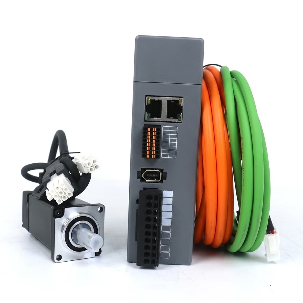
EtherCAT vs CANopen for Multi-Axis Robotic Actuation
Analyzing the real-world latency, synchronization, and cost trade-offs of EtherCAT versus CANopen in custom multi-axis servo drives.
Executive Summary (TL;DR)
- CANopen is robust, cheap, and simple to route, but capped at 1 Mbps with 100-250 Hz update rates, making it suitable only for point-to-point motion like AGVs.
- EtherCAT enables sub-millisecond, highly synchronized 1,000Hz+ control loops via Distributed Clocks, which is mandatory for impedance control in humanoids and surgical arms.
- Implementing EtherCAT adds roughly $10-$15 to the BOM per joint and requires bulkier Cat5e cabling compared to a 2-wire CAN bus.
- Modern hybrid architectures often combine an EtherCAT backbone for high-bandwidth motion with a CAN sub-bus for localized sensor fusion.
For low-voltage axes, pair the protocol decision with the 24V servo drive sizing guide to check bus demand, motor data and regenerative energy before requesting a drive quote.
For axes on a 48V bus, the 48V servo drive selection guide separates DC supply demand from motor phase current and lists the encoder, protocol and battery evidence needed for an RFQ.
The Nervous System of the Robot
In multi-axis robotics, such as a 6-DOF robotic arm or a 20-DOF humanoid, the servo motors are the muscles, but the communication protocol is the nervous system. The speed and deterministic reliability of this network dictate how fluid, responsive, and safe the robot will be.
Two protocols dominate the modern custom servo drive landscape: CANopen (over CAN bus) and EtherCAT (over Ethernet). Choosing the right protocol during the OEM design phase drastically impacts the PCBA footprint, microcontroller selection, and overall bill of materials (BOM).
Protocol Comparison: By the Numbers
| Parameter | EtherCAT | CANopen |
|---|---|---|
| Physical Layer | 100BASE-TX (Ethernet) | CAN 2.0A/B (Differential Pair) |
| Max Bandwidth | 100 Mbps (Full Duplex) | 1 Mbps (Half Duplex) |
| Typical Cycle Time | 0.1 ms – 1 ms (1-10 kHz) | 5 ms – 20 ms (50-200 Hz) |
| Max Nodes | 65,535 per segment | 127 |
| Jitter | < 1 µs | > 50 µs |
| Sync Accuracy | < 100 ns (Distributed Clocks) | ~10-100 µs (SYNC Message) |
| Cable Type | Cat5e (4-8 wires, 100 Ω) | Twisted Pair (2 wires, 120 Ω) |
| BOM Cost/Node | ~$10-$15 (ESC + PHY + Mag) | < $1 (Transceiver, often on MCU) |
| Topology | Line, Tree, Star (Daisy-chain typical) | Bus (Daisy-chain) |
Latency Budget Analysis
In advanced multi-axis robotics, total system latency dictates the maximum stable bandwidth of your impedance control loops. A 1 kHz control loop implies a 1 ms budget for the entire data trip.
| Component | EtherCAT Latency (µs) | CANopen Latency (µs) @ 1 Mbps |
|---|---|---|
| Controller Output Processing | 15 - 50 | 50 - 100 |
| Network Transit (6 axes) | ~10 - 15 | ~800 - 1,200 |
| Slave Node Processing | 1 - 2 (Hardware ESC) | 50 - 100 (Software MCU) |
| Current Loop Execution | ~50 - 100 | ~50 - 100 |
| Total Round-Trip Time | < 100 µs | > 1,000 µs (1 ms+) |
Because EtherCAT processes frames "on the fly" in hardware, network transit latency scales linearly and very slowly with node count (approx. 1 µs per node). CANopen relies on individual message arbitration, meaning latency scales dramatically as nodes are added.
CiA 402 vs CoE: Speaking the Same Motion Language
While the physical and data link layers differ drastically, both protocols can speak the exact same motion language: the CiA 402 Device Profile for Drives and Motion Control.
When running EtherCAT, this is referred to as CoE (CAN application protocol over EtherCAT). This means your high-level control software interacts with the Object Dictionary (Index and Sub-index) identically whether you use CAN or EtherCAT.
Core Modes of Operation
- Cyclic Synchronous Position/Velocity/Torque (CSP, CSV, CST)
- Protocol: Dominated by EtherCAT.
- How it works: The master sends fresh setpoints every cycle (e.g., every 1 ms). The drive blindly executes the setpoint, trusting the master's trajectory planner. Requires Distributed Clocks (DC) to prevent jitter.
- Use Case: Humanoids, dynamic quadrupeds, surgical arms.
- Profile Position / Profile Velocity Mode (PP, PV)
- Protocol: Ideal for CANopen.
- How it works: The master sends a target position, max velocity, and acceleration limits. The local servo drive's MCU calculates the trajectory profile.
- Use Case: AGVs, camera gimbals, simple indexing axes.
PCBA Hardware Impact: What Changes on the Board?
Designing a drive for EtherCAT requires significantly more board real-estate and component count than CANopen. This translates directly to the BOM cost and form factor constraints—a crucial factor when designing Custom Servo Drives for tight robotic joints.
| Hardware Aspect | EtherCAT Board Impact | CANopen Board Impact |
|---|---|---|
| MAC/Controller | Dedicated ESC ASIC (e.g., AX58100, ET1100) or integrated high-end MCU (e.g., TI C2000) | Native in almost all standard MCUs (STM32, NXP) |
| Physical Layer (PHY) | Dual 100BASE-TX PHYs required | Single CAN Transceiver IC (e.g., TCAN1051) |
| Clock / Crystal | High-precision 25 MHz crystal for ESC | Standard MCU crystal |
| Connectors & Magnetics | 2x RJ45 or robust board-to-board with integrated magnetics | Simple 3-pin or 4-pin header |
| PCB Real Estate | + 400-600 mm² | + 50 mm² |
| BOM Premium | + $10 to $15 per drive | Negligible |
Real-World Performance Comparison
Let's look at achievable cyclic update rates in multi-axis setups.
| Robot Type | Axes Count | Protocol | Max Stable Update Rate | Sync Jitter | Network Load |
|---|---|---|---|---|---|
| 6-Axis Arm | 6 | CANopen (1 Mbps) | ~200 Hz | ~50 µs | 85% |
| 6-Axis Arm | 6 | EtherCAT | 4,000 Hz | < 0.1 µs | < 5% |
| Humanoid | 20 | CANopen (1 Mbps) | ~50 Hz (Not Recommended) | > 100 µs | 95% |
| Humanoid | 20 | EtherCAT | 1,000 - 2,000 Hz | < 0.1 µs | < 10% |
The Hybrid Architecture: Best of Both Worlds
In highly complex robots, relying on a single communication bus can be inefficient. Modern robotic architectures frequently employ a hybrid approach:
- The EtherCAT Backbone: Used exclusively for high-bandwidth, tightly synchronized motor control (CST or CSP modes).
- The CANopen Sub-bus: Used for localized sensor networks, such as absolute encoders, force-torque sensors, or simple end-effector grippers.
By offloading low-bandwidth sensor data to a CAN sub-bus, the EtherCAT network remains deterministic and uncluttered, maximizing the control loop frequency for the primary actuators.
Migration Path: Designing a Dual-Protocol Servo Drive
For OEMs uncertain about their final protocol requirements, it is possible to design a unified PCBA that supports both, mitigating the Hidden Costs in Custom Robot Servo OEM Manufacturing.
The Modular Approach:
- Base Control Board: Houses the MCU, inverter stage, and CAN transceiver.
- Piggyback Communication Module: A small mezzanine board containing the EtherCAT ESC, PHYs, and magnetics.
- SPI Interface: The MCU communicates with the ESC via SPI. If EtherCAT is not required, the piggyback board is omitted, and the MCU routes data directly through its native CAN interface.
This allows a single base PCBA to scale from simple AGV tasks to complex impedance-controlled robotic applications without a complete redesign.
Protocol Decision Matrix
Final Thoughts
The decision between EtherCAT and CANopen is ultimately a trade-off between control bandwidth and implementation cost. By understanding these trade-offs early in the design phase, and potentially choosing a dual-protocol migration path, you can avoid costly redesigns later.
If you are currently evaluating motor technologies to pair with your drive network, check out our guide on BLDC vs PMSM in Custom Servo Motors.
Inquiry Email
Include drawings, torque/speed, protocol, and prototype quantity.
Author

Categories
More Posts
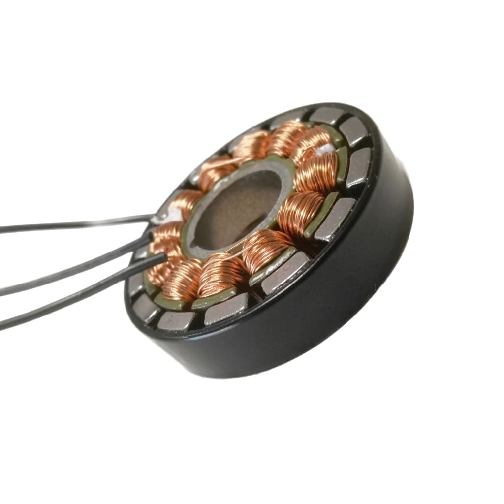
BLDC vs PMSM for Custom Robot Servos: Which Motor Architecture Wins?
An engineering comparison between Brushless DC (BLDC) and Permanent Magnet Synchronous Motors (PMSM) for high-performance robotics actuation.
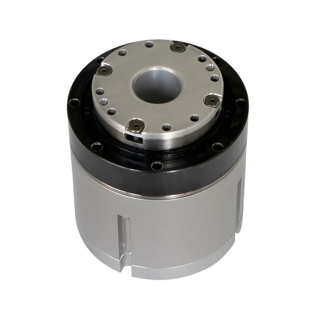
Unboxing the Backlash Blackbox: Harmonic vs Cycloidal vs Planetary for Robotic Joints
A deep engineering guide to choosing between Harmonic, Cycloidal, and Planetary reducers for custom robotic joints to manage backlash, rigidity, and shock loads.
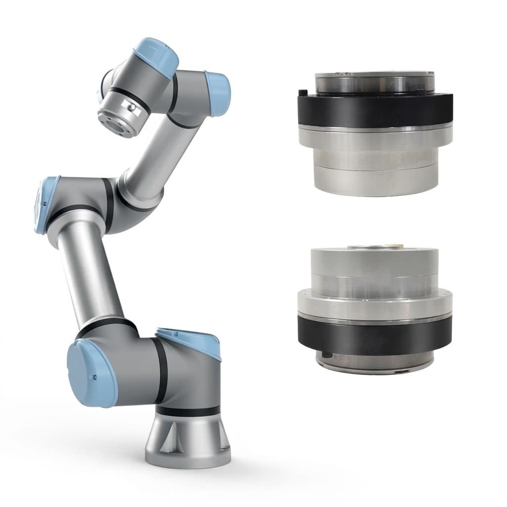
Custom Robot Servo RFQ Guide for Robotics OEM Buyers
How to prepare a useful custom robot servo inquiry across servo motors, servo drives, smart servos, and integrated robotic actuator assemblies. Avoid quote loops and hidden NRE traps.