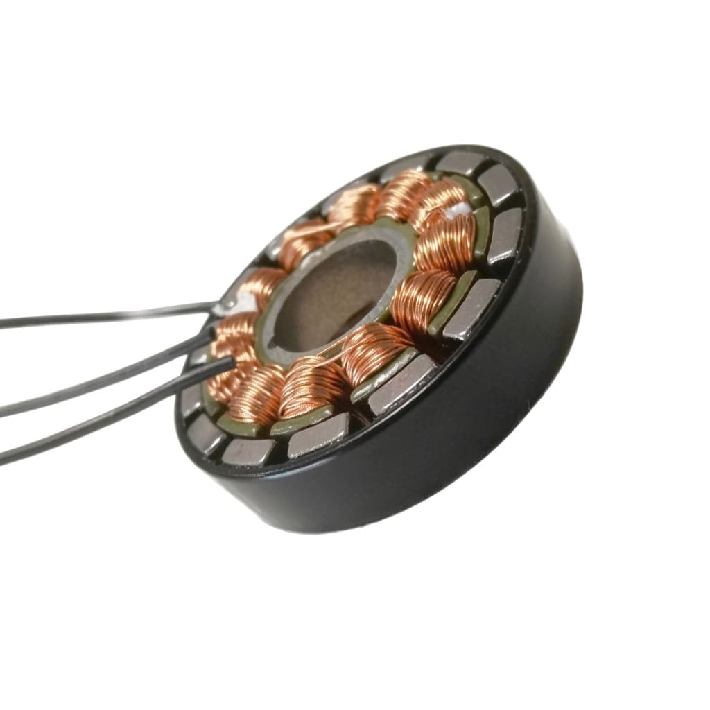
BLDC vs PMSM for Custom Robot Servos: Which Motor Architecture Wins?
An engineering comparison between Brushless DC (BLDC) and Permanent Magnet Synchronous Motors (PMSM) for high-performance robotics actuation.
Executive Summary (TL;DR)
- BLDC motors with trapezoidal EMF and block commutation are cost-effective for AGV drive wheels but suffer from torque ripple.
- PMSM motors with sinusoidal EMF and FOC drives are mandatory for humanoid joints and cobots requiring low-ripple standstill torque and accurate force-feedback.
- Motor constant (Km) and stator architecture strictly limit a servo's absolute performance ceiling, regardless of the servo drive's software capabilities.
Core Architecture: Selecting the Right Electromagnetic Topology
When designing a custom robot servo, the physical construction of the bare motor sets the absolute ceiling for torque density, efficiency, and torque ripple. No amount of advanced control algorithms on the servo drive can compensate for a fundamentally mismatched motor.
For high-performance robotics—such as humanoid joints, surgical arms, and precision cobots—the debate almost always narrows down to two dominant brushless topologies: BLDC (Brushless DC Motor) and PMSM (Permanent Magnet Synchronous Motor).
While both are synchronous motors relying on permanent magnets on the rotor and wound coils on the stator, their back-EMF waveforms, stator winding methods, and optimal control strategies differ drastically.
The Back-EMF Waveform Difference
The fundamental difference lies in the back-Electromotive Force (back-EMF) waveform generated when the motor is spun.
Comprehensive Comparison Table
To compare these technologies practically for servo design, we must look at the electromagnetic behavior alongside the electronics required to drive them.
| Parameter | BLDC (Brushless DC) | PMSM (Permanent Magnet Synchronous) |
|---|---|---|
| Back-EMF Waveform | Trapezoidal | Sinusoidal |
| Commutation Method | 6-Step Block / Trapezoidal | FOC (Field Oriented Control) / SVPWM |
| Torque Ripple (%) | 10% - 15% | 1% - 3% |
| Typical Efficiency | 80% - 88% | 88% - 94% |
| Control Complexity | Low to Medium | High (Requires Park/Clarke transforms) |
| Encoder Requirement | 3x Hall Sensors (3-bit) or basic optical | High-res absolute magnetic/optical (17 to 23-bit) |
| BOM Cost Impact | Lower (cheaper MCU, no absolute encoder) | Higher (FOC MCU, precision encoder) |
| Best Robotics Application | AGV wheels, conveyor drives | Humanoid joints, cobots, surgical arms |
Motor Constant Analysis: The True Measure of Efficiency
When evaluating custom servo motors, the most critical parameter is often the Motor Constant (Km) rather than just the Torque Constant (Kt).
- Torque Constant (Kt): Measured in Nm/A. Represents how much torque is generated per amp of phase current. It changes if you rewind the motor with different gauge wire.
- Motor Constant (Km): Measured in Nm/√W. Represents the true efficiency of transforming electrical power into mechanical torque, independent of the winding configuration. The formula is: Km = Kt / √(R_line).
Higher Km means less heat (I²R losses) is generated for a given torque. PMSM stators typically achieve higher Km due to higher copper fill factors and optimized magnet pole designs.
| Motor OD | BLDC Typical Km (Nm/√W) | PMSM Typical Km (Nm/√W) | What to Check / Red Flag |
|---|---|---|---|
| 40mm | 0.02 - 0.04 | 0.03 - 0.05 | Core losses at high RPM |
| 60mm | 0.06 - 0.10 | 0.08 - 0.14 | Stator winding density (slot fill factor) |
| 80mm | 0.15 - 0.25 | 0.20 - 0.35 | Magnet grade degradation (N42SH vs N52H) |
| 100mm | 0.35 - 0.60 | 0.50 - 0.85 | Active length vs wasted end turns |
For a deep dive into how Km relates to continuous torque and cooling, read our guide on thermal derating physics in robot servos.
Buyer Decision Matrix
Use this decision tree to determine which architecture is best for your custom axis.
Drive Architecture Impact
Choosing between BLDC and PMSM dictates what your servo drive electronics must be capable of.
| Drive Component | BLDC Requirement | PMSM Requirement | Performance Impact |
|---|---|---|---|
| MCU Type | Basic 32-bit (e.g., STM32F1) | DSP / High-end 32-bit (e.g., TI C2000, STM32G4) | Computation speed for FOC math (Park/Clarke transforms) |
| PWM Frequency | 10 kHz - 20 kHz | 20 kHz - 100 kHz | Higher frequency needed to synthesize smooth sine waves |
| Current Loop BW | 1 kHz - 2 kHz | 3 kHz - 5 kHz+ | Stiffer, more responsive torque control for PMSM |
| Encoder Resolution | 3-bit (Hall effect) | 17-bit to 23-bit absolute | FOC needs exact rotor angle to perfectly align magnetic fields |
Integrating these drives into a wider robotic system requires a solid communication protocol. Learn more in our EtherCAT vs CANopen for multi-axis robotics guide.
Real-World Application Matrix
| Robot Type | Recommended Motor | Reasoning | Acceptable Range |
|---|---|---|---|
| Humanoid Joints | PMSM (Frameless) | Requires absolute minimum torque ripple, ultra-compact integration with harmonic drives, and precise impedance control. | < 2% Ripple, Km > 0.15 |
| Cobot Arms | PMSM | Force sensing without external torque sensors relies on pure motor current. BLDC ripple ruins this estimation. | < 2% Ripple, Km > 0.20 |
| AGV/AMR Traction | BLDC / Hybrid | Rubber wheels absorb torque ripple. Lower cost is critical for scaling fleet deployments. | 5-10% Ripple, high Kv |
| Surgical Robots | PMSM (Slotless) | Zero cogging torque required for haptic feedback and incredibly smooth teleoperation. | < 1% Ripple, Slotless |
| Exoskeletons | PMSM (High-Pole) | High torque density and efficiency needed to extend battery life and reduce wearer burden. | High Km, Low profile |
Common Procurement Mistakes
When sourcing motors for new robotic prototypes, engineers frequently fall into these traps:
- Ignoring the Km / Thermal Relationship: Selecting a high Kv BLDC when a low Kv / high Km PMSM is needed for low-speed, high-torque holding. This results in massive thermal failures at standstill.
- Over-specifying the Drive for a Cheap Motor: Running a state-of-the-art FOC EtherCAT drive on a poorly wound BLDC with a trapezoidal back-EMF. You won't magically get PMSM smoothness out of a BLDC stator.
- Mismatched Encoder Types: Purchasing a high-end PMSM but pairing it with a cheap incremental encoder without index pulses. FOC relies completely on knowing the absolute electrical angle at startup.
- Underestimating Cogging Torque: Not testing the un-energized cogging torque of a PMSM before mating it with a harmonic drive. This can lead to periodic vibrations that severely damage the wave generator bearing over time.
- Evaluating "Rated Torque" Without Cooling Context: A motor's rated continuous torque on a datasheet is only true at a specific ambient temperature mounted to a massive aluminum heatsink. Always ask for the continuous torque without active cooling if placing the motor inside an enclosed, non-conductive joint.
If you are ready to explore physical architectures for your next robotic joint, view our capabilities in custom servo motors.
Inquiry Email
Include drawings, torque/speed, protocol, and prototype quantity.
Author

Categories
More Posts
The Hidden Costs in Custom Robot Servo OEM Manufacturing
A transparent breakdown of tooling, NRE, PCBA, and supply chain costs when scaling custom robotic joints from prototype to mass production.
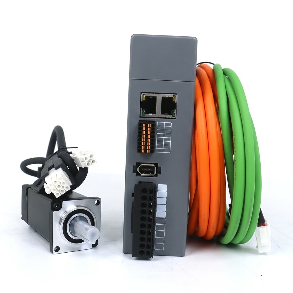
EtherCAT vs CANopen for Multi-Axis Robotic Actuation
Analyzing the real-world latency, synchronization, and cost trade-offs of EtherCAT versus CANopen in custom multi-axis servo drives.
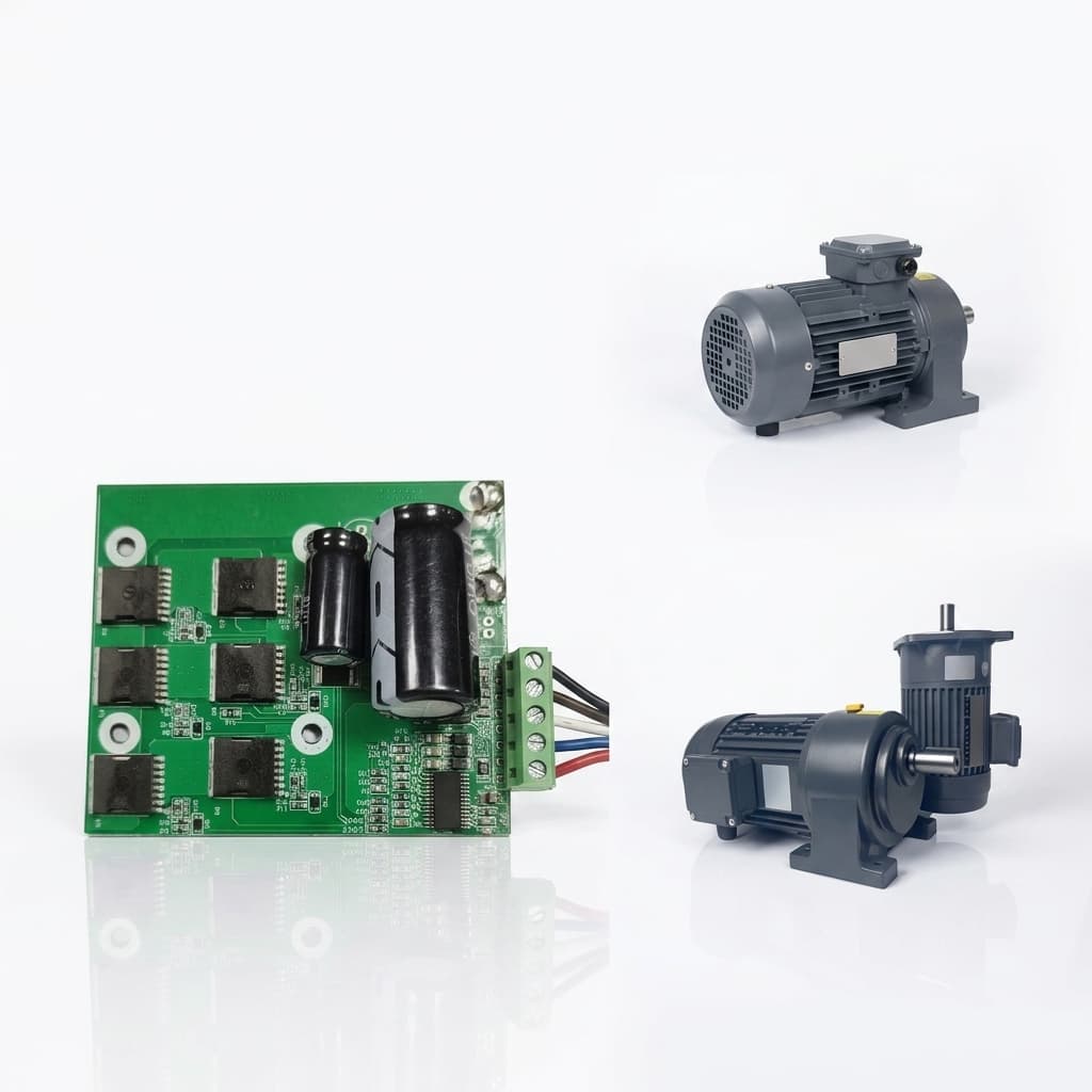
The Physics of Thermal Derating in Robot Servos: Beyond the Datasheet
Why datasheet peak torque is a trap, and how thermal derating, motor constants (Km), thermal resistance (Rth), and potting define real robot performance.