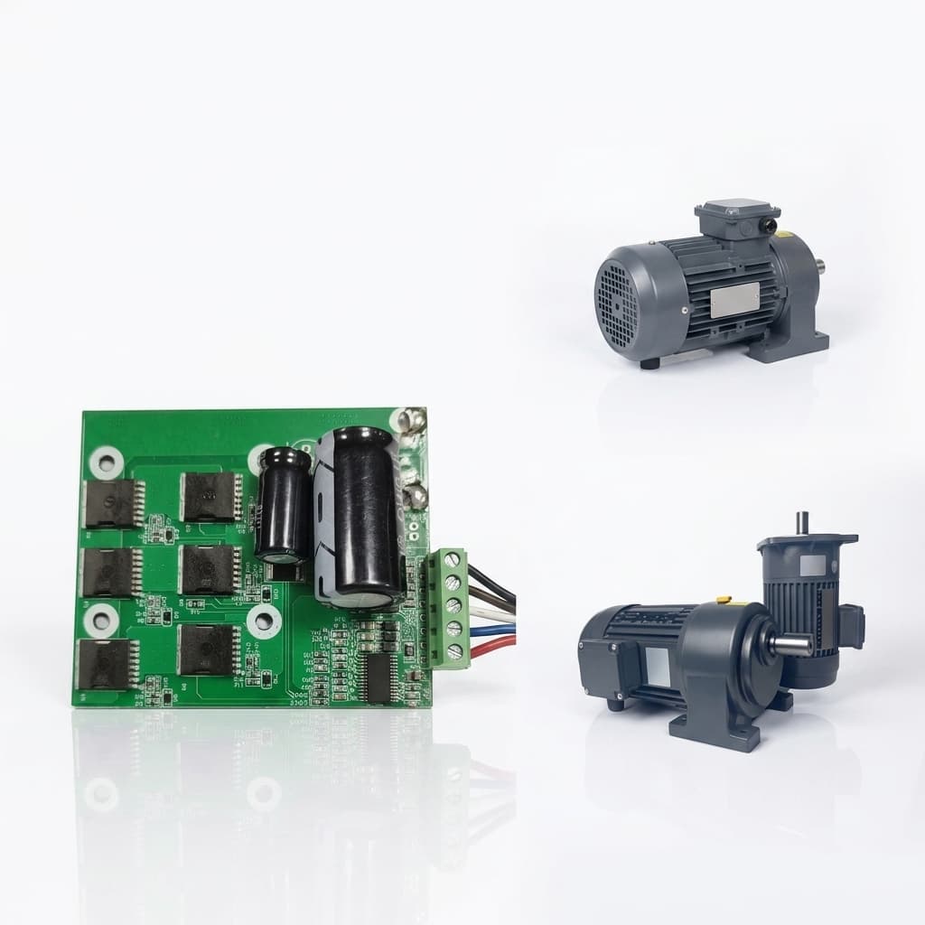
The Physics of Thermal Derating in Robot Servos: Beyond the Datasheet
Why datasheet peak torque is a trap, and how thermal derating, motor constants (Km), thermal resistance (Rth), and potting define real robot performance.
Executive Summary (TL;DR)
- Datasheet peak torque is often tested in 25°C open-air with an infinite heatsink, which severely misrepresents the enclosed IP67 robotic joint environment.
- Real-world thermal limits are determined by the 0.75x Continuous Torque Rule, thermal resistance (Rth), and motor constant (Km).
- Heat constraints can be physically mitigated using high-temp SH/UH/EH neodymium magnets, epoxy potting for lower internal Rth, and deep-stator PT1000 thermistors.
- Proper simulation requires analyzing the full thermal resistance chain from winding to ambient.
The "Datasheet Deception" in Peak Torque
In the robotics servo industry, one of the most dangerous traps for a mechanical or electrical engineer is selecting a motor based on the "Peak Torque" or "Continuous Torque" listed in standard promotional datasheets.
Suppliers often test their motors in a 25°C open-air laboratory environment, bolted to a massive 250mm x 250mm x 12mm aluminum heatsink plate. Under these ideal conditions, the motor's housing-to-ambient thermal resistance (R_th_ha) is exceptionally low (e.g., 0.8 °C/W). Convection is perfect, and conduction is infinite.
However, in reality, your custom robot servo is often sealed inside a tight, IP67-rated joint housing with zero airflow. It might be mounted to carbon fiber (a thermal insulator) or thin-walled aluminum arms that act as terrible heat conductors. When installed in the actual robot, the true thermal resistance can easily spike to 2.4 °C/W or higher.
A motor that can safely dissipate 118 watts of heat in the supplier's lab might only be able to dissipate 33 watts inside your robot joint. If pushed to its datasheet limits, the internal copper windings will rapidly breach the 120°C-155°C insulation limits (Class E or Class F), leading to short circuits and catastrophic failure.
Understanding Thermal Resistance (R_th)
Heat generation in a servo motor is primarily driven by Copper Losses (I²R). As the copper windings heat up, their electrical resistance increases (approx 0.39% per °C). This means to maintain the same torque, the drive must pump more current, generating more heat—a vicious cycle known as thermal runaway.
To calculate if a motor will survive, you must map the entire thermal resistance chain.
Delta T = P_loss * (R_th_wh + R_th_ha)
Where:
- P_loss: Power dissipated as heat (Watts).
- R_th_wh: Thermal resistance from the winding to the motor housing (internal to the motor).
- R_th_ha: Thermal resistance from the housing to the ambient environment (dependent entirely on your robot's design).
If (Delta T + Ambient Temp) > 155°C, the motor fails.
Thermal Resistance Comparison by Mounting Scenario
| Mounting Scenario | R_th_ha (°C/W) | Max Continuous Power (W) | Achievable Continuous Torque (% of Datasheet) |
|---|---|---|---|
| Open air bench (Infinite heatsink) | 0.8 | 118 | 100% |
| Aluminum heatsink plate | 1.2 | 80 | ~82% |
| Aluminum joint housing (Enclosed) | 2.1 | 45 | ~61% |
| Carbon fiber arm, sealed | 3.5 | 27 | ~45% |
| Plastic housing, sealed | 4.2 | 22 | ~40% |
Temperature Rise Calculation Walkthrough
Step 1: Identify Knowns
Consider a custom 60mm OD BLDC servo motor.
- Max winding temperature limit (Class F insulation): 155°C
- Ambient environment temperature: 40°C
- Internal thermal resistance (R_th_wh): 0.5 °C/W
- Housing-to-ambient resistance (R_th_ha) in an enclosed aluminum joint: 2.1 °C/W
- Total R_th = 2.6 °C/W
Step 2: Calculate Allowable Delta T
Allowable Temperature Rise (ΔT) = 155°C - 40°C = 115°C
Step 3: Calculate Max Power Dissipation (P_loss)
Max continuous heat dissipation (Watts) = ΔT / Total R_th P_loss = 115°C / 2.6 °C/W = 44.2 Watts
Step 4: Determine Actual Current Limit
Knowing the motor's terminal resistance (e.g., 0.8 Ohms at 25°C, rising to ~1.2 Ohms at 155°C due to the copper temperature coefficient of 0.00393/°C). P_loss = I² * R 44.2W = I² * 1.2Ω I = √(44.2 / 1.2) = 6.07 Amps RMS
Step 5: Convert to Continuous Torque
If the torque constant (Kt) is 0.15 Nm/A: Max Continuous Torque = 6.07A * 0.15 Nm/A = 0.91 Nm. If the datasheet claims 1.5 Nm continuous (tested on a perfect heatsink), your real-world torque is drastically derated to just 60% of the spec.
The 0.75x Continuous Torque Rule
To avoid thermal shutdown or permanent demagnetization of the rotor magnets, we strongly advise our OEM clients to follow the 0.75x Continuous Torque Rule during the initial RFQ phase.
The actual continuous RMS load required by your application should never exceed 75% of the supplier's rated continuous capability.
This 25% safety margin is non-negotiable for early-stage design. It absorbs heat accumulation from aggressive, high-frequency duty cycles, instantaneous shock loads, and the highly constrained thermal environment of enclosed robotic joints.
Magnet Grade Selection Matrix
High operating temperatures don't just threaten windings; they cause irreversible demagnetization of the rotor.
| NdFeB Grade | Max Operating Temp (°C) | Br at 20°C (T) | Br at 100°C (T) | Cost Multiplier | Recommended Application |
|---|---|---|---|---|---|
| N35 | 80°C | 1.17 - 1.21 | ~1.05 | 1.0x | Low-cost consumer robotics |
| N38SH | 150°C | 1.22 - 1.25 | ~1.12 | 1.4x | Standard industrial robotic joints |
| N42UH | 180°C | 1.28 - 1.32 | ~1.18 | 1.8x | High-performance compact actuators |
| N45EH | 200°C | 1.32 - 1.38 | ~1.24 | 2.5x | Extreme environments, heavy payload arms |
Solving Thermal Issues with Custom Engineering
When standard motors fail thermal validation, the solution isn't always to select a physically larger, heavier motor (which ruins the robot's power-to-weight ratio). As a full-stack custom robot servo manufacturer, we attack thermal limits through physics:
- High Motor Constant (Km): We optimize the winding topology and lamination design to maximize Km (torque per square root of power, Nm/√W). This is the purest metric of a motor's thermal efficiency. A higher Km means less heat generated for the same torque.
- Advanced Thermal Potting: The air gap between the stator laminations and the outer housing is a thermal bottleneck. We eliminate insulative air gaps using high-thermal-conductivity epoxy potting compounds, drastically lowering R_th_wh.
- High-Temp Neodymium Magnets: Standard N35 magnets will permanently lose magnetic flux (demagnetize) above 80°C. We deploy SH (150°C), UH (180°C), or EH (200°C) grade NdFeB magnets to ensure the rotor survives aggressive heat spikes without permanent torque degradation.
- Embedded Thermal Sensing: We embed custom PT1000 or dual NTC thermistors deep inside the stator windings—not just on the housing—to provide the servo drive with real-time, highly accurate thermal data, allowing the drive to fold back current safely before destruction occurs.
Embedded Sensor Selection: The Last Line of Defense
To prevent thermal runaway, temperature sensors must be strategically placed deep in the stator windings—not just taped to the housing.
| Sensor Type | Accuracy | Response Time | Cost Impact | Placement Strategy | Servo Drive Integration |
|---|---|---|---|---|---|
| PT1000 | Very High (±0.3°C) | Moderate (1-2s) | High ($3-5) | Deep within phase windings | Linear curve, easily read by high-end drives |
| NTC Thermistor | Medium (±1.5°C) | Fast (<1s) | Low ($0.50) | Glued to winding end turns | Non-linear, requires lookup table |
| Thermocouple (Type K) | High (±1°C) | Very Fast | High ($5+) | Lab testing only (Not prod) | Requires specialized cold-junction IC |
For highly enclosed custom robotic joints, we standardize on PT1000 sensors embedded during the stator winding phase and locked in place with thermal epoxy.
The Derating Curve: Navigating the Safe Operating Area
A proper thermal derating curve clearly maps out the maximum continuous torque available as a function of the ambient temperature. As the ambient temperature rises, the available ΔT shrinks, severely limiting power dissipation.
Thermal Simulation Checklist for RFQ
Before purchasing custom servo motors, buyers must provide accurate thermal context. Don't fall for the hidden costs in custom robot servo OEM manufacturing.
Provide your servo supplier with this checklist:
- Duty Cycle Profile: RMS torque requirement, not just peak torque. Peak duration (e.g., 200% for 2 seconds).
- Mounting Materials: Material thermal conductivities and thicknesses (e.g., 4mm Aluminum 6061 vs 3mm Carbon Fiber).
- Ambient Temperature Range: Minimum, nominal, and maximum ambient limits.
- Enclosure Type: Open air, ventilated, or IP67 sealed.
- Cooling Mechanisms: Passive convection, forced air, or liquid cooling lines.
Inquiry Email
Include drawings, torque/speed, protocol, and prototype quantity.
Author

Categories
More Posts
Unboxing the Backlash Blackbox: Harmonic vs Cycloidal vs Planetary for Robotic Joints
A deep engineering guide to choosing between Harmonic, Cycloidal, and Planetary reducers for custom robotic joints to manage backlash, rigidity, and shock loads.
The Hidden Costs in Custom Robot Servo OEM Manufacturing
A transparent breakdown of tooling, NRE, PCBA, and supply chain costs when scaling custom robotic joints from prototype to mass production.
EtherCAT vs CANopen for Multi-Axis Robotic Actuation
Analyzing the real-world latency, synchronization, and cost trade-offs of EtherCAT versus CANopen in custom multi-axis servo drives.