
1. What the screening can decide
Use the tool to identify constraints before requesting a CANopen servo drive for dexterous robot hands. These are calculated examples, not product ratings or measured benchmarks. The default is a discrete-node baseline; the reduced packed map is an explicit alternative.
4.375 ms wire time
16 axes, one 8-byte command and feedback per axis, 1 Mbps. A 2.5 ms cycle cannot fit. See section 4.
1.875 A ripple
24 V, 40 uH effective inductance, 80 kHz in the stated PWM approximation. Frequency alone does not qualify the motor. See section 6.
7.2 N available grip
A 12 N modeled target with 40% holding-current reduction loses 40% of its force. See section 3.
Drive-only heat
The entered budget is an allocation after reserving motor and other heat. No universal 14 W palm limit is established. See section 7.
Protocol evidence: CiA frame structure and PDO mapping. Ripple context: maxon PWM guidance. Force and heat figures follow the equations and assumptions in section 13.
2. Choose the mechanical force path first
Mechanical packaging determines whether a compact drive is useful. The following is an engineering trade-off framework; mass, friction and temperature values need your own CAD and tests.
Use the fingertip contact moment arm. Include tendon spool geometry in the effective reduction; coupled fingers need a calibrated force-path model.
| Location | Decision benefit | Cost or failure risk | Evidence to request |
|---|---|---|---|
| In-palm tendon | Lower distal moving mass | Tendon wear, friction and assembly work | Routing CAD; force calibration across poses |
| In-joint | Shorter transmission path | Knuckle mass, volume and local heat | Joint thermal path; cable-flex tests |
| Forearm remote | More palm space and cooling area | Long tendon paths and compliance | Bend-dependent hysteresis and service plan |
For tendon mechanisms, enter the contact-force moment arm rather than a spool radius. The effective reduction must include spool geometry. For coupled or underactuated fingers, use a calibrated equivalent axis model; equal loads on all axes are an approximation.
3. Keep the grip-force target visible when reducing current
Required holding torque is F_tip * r_contact. Motor current is that torque divided by effective reduction, efficiency and the phase-RMS torque constant. Dynamic torque additionally uses the supplied joint-side inertia times acceleration; the default inertia is illustrative.
Current reduction lowers force proportionally in this model. A 50% reduction cuts the holding resistive-loss term by 75%, while halving force; total system heat is not reduced by that same percentage.
| Current reduction | Modeled available force | Holding I2R loss vs baseline | Decision |
|---|---|---|---|
| 0% | 12 N | 100% | Meets the algebraic force target; verify grip margin |
| 40% | 7.2 N | 36% | Force target is missed unless another mechanism supports the load |
| 50% | 6 N | 25% | 75% reduction applies only to the holding resistive term, not total heat |
Reducing current is not an automatic thermal remedy. Restore the required force, reduce a separately validated duty cycle, improve conduction or qualify a brake/latch. Test slip and release behavior for the intended object and orientation.
4. Budget the actual bytes on each CAN channel
The timing model uses 11-bit identifiers, 135 bit times per 8-byte PDO and 55 per zero-byte SYNC, including stuffing allowance and intermission. This is cyclic serialization time without heartbeat, EMCY, SDO, tactile traffic, errors or retries.
At 1 Mbps, modeled wire times are 4,375 us discrete and 1,675 us with the reduced vendor-specific map. Four-axis hardware alone does not establish that map or cycle stability.
| Architecture | PDOs on busiest segment | Wire time including SYNC | Cycle share | Limitation |
|---|---|---|---|---|
| Discrete baseline | 32 | 4,375 us | 175% | Cannot fit this cycle; at least 7.5 ms targets <=60% share |
| Vendor-specific 4-axis packed map | 12 | 1,675 us | 67% | Reduced map only; >=3 ms targets <=60%; EDS confirmation required |
| Dual CAN, 8 axes/channel | 16 per channel | 2,215 us per channel | 88.6% | Own SYNC per channel; >=4 ms targets <=60% |
Flags are planning heuristics: below 60%, 60–75%, 75–85%, and 85%+. A share of 85% is not a CAN physical limit; 100%+ cannot fit. Lower occupancy still needs a worst-case latency test and priority analysis. Odd dual-bus axis counts are rounded up only on the busiest segment.
Reference: CiA: Classic CAN. Base-frame fields, 8-byte payload, intermission, bit stuffing and arbitration. Our 135/55-bit allowances exclude errors and retries.
Reference: CiA: Special function protocols. SYNC and emergency protocol context. Actual scheduling and message rates need a bus capture.
5. Treat packed multi-axis PDOs as an integration contract
A four-axis PCB does not inherently reduce traffic. Our optional three-frame example deliberately reduces data width and cadence. It does not represent a standard full CiA 402 cyclic synchronous position map.
| PDO | Content | Bytes | Missing or conditional information |
|---|---|---|---|
| RPDO | 4 x 16-bit commands | 8 | No cyclic per-axis controlwords; position width/units are vendor-specific |
| TPDO 1 | 4 x 16-bit reduced positions | 8 | Not four full 32-bit position objects |
| TPDO 2 | 4 x 16-bit status fields | 8 | No temperature or tactile values included |
Before accepting the lower load figure, require the EDS/object dictionary, mode support, scaling, wrap behavior, controlword update schedule, timeout handling and all omitted message rates. If that contract is unavailable, keep the discrete baseline and count any additional frames.
Reference: CiA: Process data objects. PDO payload and mapping rules. Does not establish that a specific drive supports our reduced 4-axis map.
Reference: CiA: 402 drive profile. Drive control profile and operating-mode context. Confirm supported modes, object widths and multi-axis implementation in the EDS.
6. Check ripple instead of prescribing a fixed PWM rate
At 24 V and 40 uH, increasing PWM from 40 to 80 kHz changes this approximation from 3.750 to 1.875 A peak-to-peak. It does not guarantee an acceptable motor temperature.
The approximation I_pp = V / (4 * f_pwm * L_eff) applies to the stated 3-level PWM worst-case model. Other modulation schemes differ. L_eff must describe the effective switching-frequency current path, including chokes; a catalog phase value may not represent that path.
| PWM rate | Peak-to-peak ripple | What follows |
|---|---|---|
| 20 kHz | 7.500 A | Review current-path inductance and current limits |
| 40 kHz | 3.750 A | Doubling frequency halves this approximation |
| 80 kHz | 1.875 A | Still above 0.2 A; no blanket acceptance |
| 120 kHz | 1.250 A | Higher switching losses and EMI still need checking |
The tool flags ripple relative to required holding current, not rated motor current. Its 20%/40% and 0.35/0.8 A flags are editorial screening thresholds. Compare measured RMS and peak currents with the selected motor/drive ratings. A choke also adds volume, copper loss and potential loop-stability work.
Reference: maxon: PWM current ripple and motor chokes. Ripple depends on voltage, PWM scheme, frequency and effective inductance. The 1/(4*f*L) approximation is conditional, not a universal BLDC formula.
7. Allocate drive heat after accounting for the rest of the palm
The tool compares illustrative electronics losses with a user-entered allocation. It has no validated enclosure thermal resistance and cannot establish palm or skin temperature.
| Term | Model treatment | Required qualification |
|---|---|---|
| Drive conduction | 3 * (I_duty_rms^2 + I_pp^2/12) * 0.024 ohm per axis | Illustrative hot-path resistance and triangular ripple; calibrate topology and temperature dependence |
| Drive switching | V * I_duty_rms * f_pwm * 40 ns per axis | Illustrative aggregate coefficient; excludes detailed commutation and gate-charge model |
| Drive logic | 0.45 W per axis | Illustrative; multi-axis shared overhead may differ |
| Motor, gears, wiring and sensors | Excluded | Reserve their measured heat before assigning the drive-only budget |
| Palm or skin temperature | Not calculated | Need ambient, thermal resistances, contact duration and component limits |
Thermal margin is the entered drive allocation minus the drive subtotal. It cannot establish a maximum palm temperature or indefinite safe holding. Measure the final glove, chassis and wrist conduction path at the worst allowed ambient and duty. If the allocation is exceeded, review cooling, electronics and a force-validated duty plan.
8. Observe transmission error before closing a second loop
An output encoder can reveal errors hidden from motor-side feedback. A second control loop requires calibration and a stability check on the actual mechanism.
Motor-side sensing supports commutation; joint-side sensing can reveal tendon stretch and gear play. A dual-loop architecture adds sensors, calibration and stability work. Compare motor angle divided by effective reduction with measured joint angle, allowing for tendon geometry and wrap; do not multiply motor angle by the reduction.
| Feedback | Can observe | Cannot establish alone | Next test |
|---|---|---|---|
| Motor encoder | Rotor position and motor speed | Actual finger contact force or all tendon stretch | Pose-dependent force calibration |
| Joint encoder | Output joint position | Contact force without a mechanism model | Joint-loop stability and dropout behavior |
| Tactile or tendon load sensing | Local contact or tendon load | Whole-hand safe state | Overload, drift and sensor fault response |
9. Separate tactile payload from motion traffic
The raw example is 49.152 Mbps before framing. Four 8-byte summaries at 100 Hz add a modeled 54 kbps, or 5.4% of a 1 Mbps link; add this traffic to the motion budget.
| Signal design | Calculation | Implication |
|---|---|---|
| Raw four-finger matrices | 4 * 256 taxels * 3 channels * 2 bytes * 1,000 Hz = 6.144 MB/s | 49.152 Mbps payload before framing; cannot fit on classic 1 Mbps CAN |
| Reduced local metrics | 4 fingertips * one 8-byte frame * 100 Hz * 135 bits = 54,000 bit/s | 5.4% extra modeled bus share before other overhead |
| Training heatmaps | Rate and compression depend on the sensor | Measure payload; use a separate interface if the budget cannot fit |
An example 8-byte summary could carry three 16-bit force components, an 8-bit slip flag and an 8-bit sequence counter. It has no center-of-pressure fields. Object indexes and layouts must come from the sensor firmware contract; no universal 0x2030 object is assumed.
10. Compare upgrade cost with the data you must retain
Higher-bandwidth alternatives change controllers, protocols, cabling and commissioning. A CAN FD transceiver alone does not upgrade classic CANopen.
| Option | When to investigate | Integration cost or constraint | Minimum evidence |
|---|---|---|---|
| Classic CANopen | Mapped bytes and rates fit with tested reserve | Limited payload; priority and scheduling work | EDS plus loaded bus capture |
| Two CAN channels | Partitionable finger groups | More controllers/harness; synchronization work | Per-channel timing and fault tests |
| CANopen FD | Need larger payloads and compatible devices | Protocol, controller and drive migration | End-to-end support and measured timing |
| EtherCAT | Need coordinated high-rate data across many axes | Master, hardware, cabling and integration change | Cycle/jitter test for selected topology |
Compare total engineering and service cost, not just drive count. Packed data can reduce wiring work while increasing firmware dependence. Two buses add hardware and do not automatically provide fault tolerance. A faster transceiver alone does not migrate classic CANopen.
11. Define a safe state for the complete hand
No certified STO hardware or reaction time is established by this page. Torque removal may leave clamping force or let an object fall; release behavior needs system validation.
No universal finger-force threshold or release latency is claimed. Public standards summaries describe scope; qualification requires the applicable full requirements and application evidence.
Torque-off can leave residual clamping force in a high-friction transmission or cause a held object to fall. This page does not establish certified STO availability, a universal stop latency or a universal finger-force threshold. Software current reduction and an ordinary shutdown input are not evidence of a qualified safety function.
For collaborative industrial applications, establish contact geometry, pressure, entrapment, gravity and failure cases using the applicable standards and a system risk assessment. Confirm component evidence and validate the selected safety architecture; do not infer certification from a planning result.
Reference: ISO/TS 15066:2016: Collaborative robots. Collaborative industrial-robot scope. No universal hand pinch limit or response time is established here; use the applicable full standard and application risk assessment.
Reference: ISO 13849-1:2023: Safety-related control systems. System design methodology; its public abstract does not prescribe a performance level for this hand or certify a drive.
Reference: IEC 61800-5-2:2016: Functional safety of drives. Safety-related drive design and validation. Does not substantiate STO availability or a response time for any offered hardware.
12. Four reproducible planning scenarios
Each row uses the named tool preset. All axes are assumed to share the same mechanical/electrical load. Figures are generated from the same evaluator as the tool, not lab measurements; change the preset above to inspect assumptions. Current reduction misses the original force target in all four illustrative presets.
| Preset and assumptions | Cycle / architecture | Bus share | Reduced grip / target | Drive-only heat / allocation | Next action |
|---|---|---|---|---|---|
| Example: Humanoid 5-Finger Hand (16-DoF, In-Palm Tendon); 24 V; 35 uH; 50 kHz | 2.5 ms; discrete_slaves | 175% on busiest segment | 7.2 / 12 N | 8.7 / 14 W | Restore grip margin; verify ripple and actual map; <=60% cycle target: 7.5 ms |
| Example: Industrial Manipulator Hand (12-DoF, High-Force Pinch); 24 V; 60 uH; 40 kHz | 4 ms; discrete_slaves | 82.38% on busiest segment | 19.6 / 28 N | 6.31 / 18 W | Restore grip margin; verify ripple and actual map; <=60% cycle target: 5.5 ms |
| Example: Adaptive Gripper Hand (6-DoF, Compact Planetary); 24 V; 110 uH; 32 kHz | 1.5 ms; discrete_slaves | 111.67% on busiest segment | 17.5 / 35 N | 3.43 / 12 W | Restore grip margin; verify ripple and actual map; <=60% cycle target: 3 ms |
| Example: Biomorphic Research Hand (20-DoF, Dual-Bus CAN); 12 V; 22 uH; 80 kHz | 2 ms; dual_bus_split | 137.75% on busiest segment | 4.4 / 8 N | 9.71 / 16 W | Restore grip margin; verify ripple and actual map; <=60% cycle target: 5 ms |
13. Methods, source scope and what still needs measurement
Published by Custom Robot Servo (CRS). The equations and software examples below support engineering screening; no physical hand or drive testing is claimed.
Reviewed 2026-10-26. Force and current use a linear torque model with a constant effective ratio and efficiency. Dynamic torque adds J_joint * acceleration. Mechanical power multiplies dynamic joint torque by joint speed; it does not validate a motor torque-speed curve, voltage headroom, saturation or controller bandwidth. Ripple and drive heat are the conditional approximations described above.
| Question | Available evidence | Status / minimum next step |
|---|---|---|
| Can the tool reproduce its equations? | Deterministic software outputs and regression checks | Software evidence; not hardware qualification |
| Does the real map fit the requested cycle? | Frame-count estimate only | Unknown: obtain EDS and loaded analyzer capture |
| Will the drive hold the object? | Reduced-force model only | Unknown: test calibrated grasp force, slip and release |
| Will the covered palm stay within limits? | Illustrative drive-only subtotal | Unknown: measure all losses and steady-state temperatures |
| Are STO, pinch response or efficiency certified? | No product certificate or raw test record supplied | Unknown: obtain applicable evidence; no PASS claimed |
- CiA: Classic CAN
Base-frame fields, 8-byte payload, intermission, bit stuffing and arbitration. Our 135/55-bit allowances exclude errors and retries.
- CiA: Process data objects
PDO payload and mapping rules. Does not establish that a specific drive supports our reduced 4-axis map.
- CiA: Special function protocols
SYNC and emergency protocol context. Actual scheduling and message rates need a bus capture.
- CiA: 402 drive profile
Drive control profile and operating-mode context. Confirm supported modes, object widths and multi-axis implementation in the EDS.
- maxon: PWM current ripple and motor chokes
Ripple depends on voltage, PWM scheme, frequency and effective inductance. The 1/(4*f*L) approximation is conditional, not a universal BLDC formula.
- ISO 13849-1:2023: Safety-related control systems
System design methodology; its public abstract does not prescribe a performance level for this hand or certify a drive.
- ISO/TS 15066:2016: Collaborative robots
Collaborative industrial-robot scope. No universal hand pinch limit or response time is established here; use the applicable full standard and application risk assessment.
- IEC 61800-5-2:2016: Functional safety of drives
Safety-related drive design and validation. Does not substantiate STO availability or a response time for any offered hardware.
Software evidence: default tool run
This is software evidence from the page, captured during the review. It is a planning-model screenshot; it provides no physical prototype, thermal, efficiency or safety test evidence.
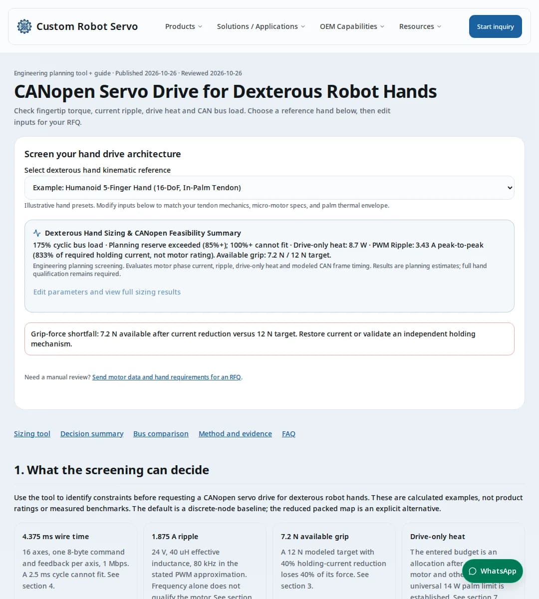
To reproduce the default: 16 axes, 1000 kbps, 2.5 ms, discrete_slaves; modeled bus share 175%, reduced grip 7.2 N, drive heat 8.7 W.
14. Engineering and RFQ questions
Architecture and procurement
Is this a catalog drive recommendation?
No. This is an architecture screen for a custom RFQ. Send motor data, CAD envelope, required modes and EDS expectations; a specific drive and its ratings still require engineering confirmation.
When should motors sit in the palm rather than the fingers?
Palm actuation can reduce distal mass but adds tendon routing, friction and service work. In-joint actuation shortens the transmission but concentrates heat and mass at the knuckle. Compare CAD, measured friction and maintainability for your hand.
Is 24 V always the best supply?
No. The 24 V preset is illustrative. Choose voltage from motor back-EMF, maximum speed, current limits, insulation and connector ratings; this tool does not calculate voltage-speed feasibility.
Does concentrating four axes guarantee lower bus traffic?
No. Bandwidth follows the mapped bytes and rates, not the PCB count. The optional packed model requires a vendor-specific reduced map. A multi-axis drive using full-width per-axis objects may require as many frames as separate nodes.
Bus timing and mapping
Can 16 axes fit a 2.5 ms classic CAN cycle?
With one 8-byte command and one 8-byte feedback PDO per axis, the modeled 1 Mbps wire time is 4.375 ms, or 175% of that cycle. The reduced packed-map example is 1.675 ms, or 67%, but omits fields and needs EDS confirmation. Neither result guarantees measured latency.
What does the packed 4-axis map contain?
One 8-byte command PDO contains four 16-bit commands. One feedback PDO contains four 16-bit positions and another four 16-bit statuses. No cyclic controlwords, temperatures or full 32-bit positions fit in that allocation. It is not a standard CiA 402 CSP mapping.
Is 85% occupancy a hard CAN limit?
No. It is a planning flag for limited reserve. At 100% or more, this modeled cyclic traffic cannot fit. Below that, deadlines can still fail because of priority, other messages, retransmissions or software jitter.
How are odd axis counts split across two CAN channels?
The reported time and load use the busiest segment, with ceil(axis count / 2) axes and one SYNC. The other segment has floor(axis count / 2) axes. Cross-channel synchronization is outside this model.
Does a CAN FD transceiver upgrade classic CANopen automatically?
No. Controller capability, the network protocol, object mapping and every participating device must support the chosen architecture. Treat CANopen FD or EtherCAT migration as a system integration project.
Motors, force and heat
Which lever arm belongs in the force calculation?
Use the perpendicular distance from the joint pivot to the fingertip contact-force line. A tendon spool radius describes a different force path. Include spool geometry in the effective motor-to-joint ratio instead.
Does reducing holding current preserve fingertip force?
Not in this model: torque and force fall in proportion to current. A 40% reduction turns a 12 N modeled target into 7.2 N. A brake, latch or other support can change that outcome only after separate qualification.
Is 50 to 80 kHz sufficient for every low-inductance motor?
No. For the stated approximation, 24 V, 40 uH and 80 kHz still produce 1.875 A peak-to-peak. Validate PWM scheme, effective inductance and permissible RMS/peak current instead of selecting by frequency alone.
Is catalog inductance the correct PWM input?
Not necessarily. Enter the effective total current-path inductance at switching frequency, including chokes. Confirm line-to-line versus phase values and the frequency dependence with the motor and drive vendors.
Are ripple flags motor rating checks?
No. The heuristic compares peak-to-peak ripple to required holding current and absolute screening thresholds. It does not know the motor continuous rating. Oscilloscope current measurements and motor RMS/peak limits remain necessary.
Does positive thermal headroom qualify the palm?
No. The result estimates drive electronics only, using illustrative coefficients and a triangular-ripple conduction allowance. Motor copper/rotor, gear, sensor and wiring losses are excluded; reserve for them before entering the drive budget.
Can the tool predict skin or encoder temperature?
No. It has no validated enclosure thermal resistance, ambient profile or component temperature limits. Measure temperatures during the worst intended grasp cycle on the complete covered hand.
Sensors, validation and safety
Why add joint-side feedback to a tendon-driven finger?
A motor encoder cannot directly observe all tendon stretch, joint play and contact deflection. An output sensor can help observe those effects; whether a second loop is needed depends on the accuracy requirement and measured stability.
Can raw tactile matrices share the motion bus?
Budget them explicitly. Four 16x16 matrices with three 16-bit channels at 1 kHz produce 6.144 MB/s before framing. That exceeds even the raw 1 Mbps link rate. Reduce data locally or provide a separate high-bandwidth path.
Does torque-off guarantee that a trapped finger is released?
No. Gear friction, tendon pretension, gravity and a brake can retain force or cause a dropped load after torque removal. Define and validate the safe state for the whole mechanism.
Are the examples physical test results or safety approval?
No. All scenario numbers are deterministic planning-model outputs. No dynamometer logs, thermal-soak records, pinch tests, certified STO hardware or system safety approval are supplied with this page.