
1. What the screening can decide
Use this tool to screen mechanical, electrical, and bus constraints before specifying a CANopen servo drive for exoskeleton robots. These figures are calculated planning models, not laboratory hardware ratings. The default is a bilateral 4-axis lower-limb rehabilitation architecture operating in CST mode over a single 1 Mbps CAN bus.
1,135 us wire time
4 axes at 1 Mbps with 1 RPDO and 1 TPDO per axis. At 1.0 ms sync, load is 113.5% (overflow); 2.0 ms cycle achieves safe 56.8% share. See section 4.
2.88 A ripple
48 V, 130 uH effective phase inductance, 32 kHz PWM. 50 kHz cuts ripple to 1.85 A p-p without heavy motor iron heating. See section 6.
41.9 Nm peak demand
40 Nm static assist plus 1.92 Nm dynamic acceleration torque at 12 rad/s2. Drive must supply 15.6 Arms peak. See section 3.
4.6 W drive loss
Inverter conduction, switching and logic losses across 4 axes. Reserved 16 W budget leaves 11.4 W margin. See section 7.
Protocol references: CiA frame structure and CiA 402 CST profile. Medical and personal care robot safety: ISO 13482 and IEC 60601-1 thermal limits. Equations and assumptions are detailed in section 13.
2. Choose the actuator reduction and transmission topology first
Actuator gear reduction dictates reflected inertia, passive backdrivability, motor size, and current requirements. For wearable systems, high reflected inertia forces active zero-torque control during unassisted swing phase, while low-ratio quasi-direct drives (QDD) require larger, heavier motors.
| Topology | Ratio range | Backdrivability and inertia | Driver requirements | Application fit |
|---|---|---|---|---|
| Quasi-Direct Drive (QDD) | 6:1 to 10:1 | Near-zero passive resistance; lowest reflected inertia (N^2 ~ 64) | High peak phase current (30–60 Arms); requires large inverter FETs | Agile gait assistance, transparent swing phase, running exoskeletons |
| Planetary Reducer | 15:1 to 35:1 | Moderate backdrivability; medium reflected inertia (N^2 ~ 600) | Balanced continuous current (8–18 Arms); compact drive PCB | Industrial lumbar lifting support, bilateral walking rehabilitation |
| Cycloidal / Harmonic | 50:1 to 100:1 | Low backdrivability; high reflected inertia (N^2 ~ 5000) | Lower motor current (3–8 Arms); higher electrical motor speed | Paraplegic standing support, locked-joint gait therapy, heavy payload |
When evaluating gearheads, verify mechanical efficiency at partial loads. At low gait cadences, friction torque can consume 15% to 25% of motor output torque.
3. Joint torque curves and dynamic acceleration demand
Human gait cycle demands asymmetric torque profiles. Peak assistance torque occurs during stance push-off (hip extension and ankle plantarflexion) or early stance loading response (knee stabilization). Total joint torque demand includes static assistance plus dynamic acceleration torque: T_total = T_assist + J_joint * joint_accel.
| Gait scenario | Joint assistance | Gear ratio | Motor peak torque | Motor peak current | Engineering takeaway |
|---|---|---|---|---|---|
| Level walking (40% assist) | 35 Nm | 36:1 (85% eff) | 1.144 Nm | 13.95 Arms | Continuous RMS current ~9.3 Arms; natural walking cadence 25 RPM |
| Stair climbing (70% assist) | 65 Nm | 36:1 (85% eff) | 2.124 Nm | 25.90 Arms | High stance torque requires inverter silicon rated for 2.0x peak current |
| Sit-to-stand transition | 80 Nm | 45:1 (82% eff) | 2.168 Nm | 24.64 Arms | Low joint speed (10 RPM) but sustained high torque holding for 1.5 seconds |
| Unassisted swing phase | 0 to 3 Nm | 36:1 (85% eff) | < 0.10 Nm | < 1.2 Arms | Active zero-torque control compensates for gear friction and inertia |
Motor phase current is calculated using phase RMS torque constant Kt. Continuous thermal rating depends on the gait stance duty cycle (typically 35% to 50% per stride).
Reference: Winter D.A., Biomechanics and Motor Control of Human Movement. Provides empirical joint torque, angular velocity, and mechanical power profiles across the 0–100% human walking gait cycle, including peak stance push-off and knee terminal swing negative work.
4. Budget the actual bytes on the CANopen bus
At 1 Mbps, each bit time is 1.0 microsecond. An 11-bit CAN frame with 8 payload bytes requires 135 bit times (including 34% bit-stuffing allowance and interframe space). A zero-byte SYNC frame requires 55 bit times. For multi-axis synchronization, serialization time across all PDOs must leave sufficient bandwidth for SDO and EMCY frames.
| Architecture | Active joints | PDOs / segment | Wire time (with SYNC) | 1.0 ms cycle load | Recommended cycle |
|---|---|---|---|---|---|
| Single CAN bus | 4 axes | 8 (4 RPDO + 4 TPDO) | 1,135 us | 113.5% (overflow) | 2.0 ms (56.8% load, optimal) |
| Dual CAN split | 4 axes (2/channel) | 4 (2 RPDO + 2 TPDO) | 595 us | 59.5% (optimal) | 1.0 ms (59.5% load, 1 kHz CST) |
| Concentrated 2-in-1 | 4 axes (2 nodes) | 4 (2 RPDO + 2 TPDO) | 595 us | 59.5% (optimal) | 1.0 ms (59.5% load, 1 kHz CST) |
| Single CAN bus | 6 axes | 12 (6 RPDO + 6 TPDO) | 1,675 us | 167.5% (overflow) | 3.0 ms (55.8% load, optimal) |
| Dual CAN split | 6 axes (3/channel) | 6 (3 RPDO + 3 TPDO) | 865 us | 86.5% (high load) | 1.5 ms (57.7% load, optimal) |
Planning thresholds: <= 60% is optimal for cyclic traffic, reserving 40% margin for asynchronous SDO parameter queries and emergency (EMCY) fault broadcasts.
Reference: CAN in Automation (CiA) CAN Physical Layer and Framing. Defines 11-bit identifier framing, 8-byte payload limits, bit stuffing rules, and physical bus bit timing up to 1 Mbps.
5. CiA 402 CST torque control and impedance loop
Wearable physical assistant robots require Cyclic Synchronous Torque (CST) mode. Position control (CSP) can cause dangerous involuntary resistance if the user stumbles or alters cadence. In CST mode, the master controller transmits target torque setpoints via RPDO, and the drive executes high-bandwidth internal FOC current control (16 kHz to 32 kHz).
| Operating mode | CiA 402 object | User interaction | Safety advantage | Wearable suitability |
|---|---|---|---|---|
| Cyclic Synchronous Torque (CST) | 0x6060 = 10 | Compliant impedance; user leads movement | Cannot overpower user joints unexpectedly | Preferred standard for walking assistance |
| Cyclic Synchronous Velocity (CSV) | 0x6060 = 9 | Active damping and speed regulation | Controlled terminal swing deceleration | Used for swing phase knee deceleration |
| Cyclic Synchronous Position (CSP) | 0x6060 = 8 | Rigid trajectory replay | Risk of joint fight or spasticity injury | Restricted to paraplegic standing therapy |
In CST mode, RPDO 1 maps Controlword (0x6040, 16-bit) and Target Torque (0x6071, 16-bit). TPDO 1 maps Statusword (0x6041, 16-bit), Actual Torque (0x6077, 16-bit), and Actual Position (0x6064, 32-bit).
| Object index | Object name | Data type & scaling | PDO direction | Control role in exoskeleton |
|---|---|---|---|---|
| 0x6071:00 | Target Torque | INT16 (per-thousand of rated torque 0x6076) | RPDO 1 (Master -> Drive) | Cyclic assistance torque setpoint from host impedance loop |
| 0x60B2:00 | Torque Offset | INT16 (per-thousand of rated torque) | RPDO 2 or RPDO 1 extension | Dynamic gravity and link inertia feedforward injection |
| 0x6072:00 | Max Torque | UINT16 (per-thousand of rated torque) | Acyclic SDO / Startup config | Hard safety clamp preventing inadvertent joint over-torque |
| 0x6077:00 | Torque Actual Value | INT16 (per-thousand of rated torque) | TPDO 1 (Drive -> Master) | Measured motor torque derived from calibrated phase currents |
| 0x6064:00 | Position Actual Value | INT32 (encoder counts per revolution) | TPDO 1 (Drive -> Master) | Absolute joint angle feedback for supervisory trajectory loop |
In a typical wearable impedance architecture, the host controller computes assistance torque via T_cmd = K * (theta_d - theta) + B * (omega_d - omega) + T_ff, where K is virtual joint stiffness, B is virtual damping, and T_ff is gravitational link feedforward. By streaming T_cmd into 0x6071 every millisecond over CANopen, the exoskeleton preserves natural human joint compliance and immediately yields to voluntary wearer stumbling motions.
Reference: CiA 402 CANopen Device Profile for Drives and Motion Control. Covers Cyclic Synchronous Torque (CST), Cyclic Synchronous Velocity (CSV), and Cyclic Synchronous Position (CSP) operating modes, statusword/controlword state transitions, and PDO communication objects.
6. Check low-inductance current ripple across PWM rates
Pancake frameless torque motors have high pole counts and short magnetic circuits, often resulting in phase inductance below 150 microhenries. Under 48 V battery supplies, standard 20 kHz PWM creates severe current ripple, generating eddy-current iron heating and DC bus capacitor stress.
| PWM frequency | Ripple current (I_pp) | Ripple % of RMS current (9.3 Arms) | Acoustic and thermal effect | Engineering recommendation |
|---|---|---|---|---|
| 20 kHz | 4.62 A p-p | 49.7% | High iron loss, audible coil whine, DC link capacitor heating | Avoid for low-inductance wearable actuators |
| 32 kHz | 2.88 A p-p | 31.0% | Substantially reduced iron heating, ultrasonic operation | Balanced baseline for silicon MOSFET inverters |
| 50 kHz | 1.85 A p-p | 19.9% | Clean sinusoidal phase currents, lowest motor copper ripple loss | Recommended for GaN or low-Qg FET drive stages |
| 80 kHz | 1.15 A p-p | 12.4% | Minimal current ripple; higher inverter switching losses | Requires low-capacitance gate drive and layout optimization |
Current ripple is modeled via the 3-level centered PWM approximation: I_pp = V_bus / (4 * f_pwm * L_phase). Confirm effective phase inductance with your motor supplier before finalizing inverter switching rates.
Reference: maxon motor: PWM power stage, Current ripple, and Motor chokes. Explains current ripple dependency on PWM frequency, DC bus voltage, and motor phase inductance in low-inductance coreless and frameless BLDC motors.
7. Drive electronics heat loss and wearable thermal barrier
Wearable medical and industrial exoskeletons are governed by IEC 60601-1 and ISO 13482, which limit applied part surface temperatures in continuous contact with human skin to 43 deg C (or 48 deg C for short durations). Inverter losses must be dissipated away from the wearer into outer aluminum structural braces.
| Loss component | Formula / model | Loss per axis | Total (4 axes) | Mitigation / design note |
|---|---|---|---|---|
| MOSFET Conduction | 3 * (I_rms^2 + I_pp^2 / 12) * R_dson | 0.41 W | 1.64 W | Low R_dson (0.015 ohm) power MOSFET stage |
| MOSFET Switching | V_bus * I_rms * f_pwm * t_switch (35 ns) | 0.50 W | 2.00 W | Fast rise/fall times via dedicated gate drivers |
| Logic & Transceiver | Microcontroller, CAN transceiver, gate logic | 0.65 W | 2.60 W | Low-power quiescent sleep modes during standby |
| Total Drive Heat | Sum of conduction, switching, and logic | 1.56 W | 6.24 W | Reserved 16 W budget leaves 9.76 W thermal margin |
Notice: This analysis models drive electronics only. Motor winding heat (which can reach 20–40 W during continuous climbing) must be isolated from the drive PCB via ceramic standoffs and directed into external convective heatsinks.
Reference: IEC 60601-1 Medical electrical equipment — General requirements for basic safety. Defines surface temperature limits for applied parts touching human skin (<= 43 deg C continuous, <= 48 deg C short-term) and electrical leakage limits for wearable medical rehabilitation systems.
8. Regenerative braking management during descent and swing
During knee terminal swing deceleration and stair descent, the human limb exerts negative mechanical work. Exoskeleton motors act as generators, pumping electrical energy back into the inverter DC bus. If the wearable battery is fully charged or its BMS opens charge FETs, this energy can cause catastrophic DC overvoltage.
| Movement phase | Mechanical braking torque | Regen power / axis | Total regen (4 axes) | Protection mechanism |
|---|---|---|---|---|
| Level walking terminal swing | 12 Nm at 25 RPM (knee) | 28.5 W | 57.0 W (2 knees) | DC link capacitors absorb transient pulse (< 100 ms) |
| Stair descent (controlled drop) | 35 Nm at 30 RPM (knee) | 83.0 W | 166.0 W (2 knees) | Dynamic braking chopper shunts energy to clamp resistor |
| Steep slope walking | 20 Nm at 25 RPM | 47.5 W | 95.0 W (2 knees) | Battery absorbs energy if SoC < 90%; chopper standby |
To protect wearable battery packs from overvoltage disconnects, compact servo drives should include an integrated dynamic braking chopper circuit that fires at 54 V (on 48 V nominal systems), dissipating excess power across a chassis-mounted power resistor.
Mathematical Proof: Why Local Capacitors Fail to Prevent Bus Overvoltage
The maximum energy a drive DC link capacitor bank of capacitance C = 680 μF can absorb when rising from nominal V_nom = 48 V to maximum allowed bus voltage V_max = 56 V is governed by:
ΔE_cap = 0.5 * C * (V_max^2 - V_nom^2) = 0.5 * 680e-6 * (56^2 - 48^2) = 0.283 Joules
During a single 150 ms knee deceleration pulse returning 50 W of electrical power, total regenerative energy is: E_pulse = 50 W * 0.15 s = 7.50 Joules. The capacitor bank can store only 3.8% of this single-step energy (0.283 J / 7.50 J). If the wearable battery BMS charge protection FET is disconnected (or at 100% state of charge), absorbing 7.50 J into 680 μF would theoretically drive the DC bus to: V_peak = sqrt(48^2 + 2 * 7.5 / 680e-6) = 156.4 V! This catastrophic 156 V surge occurs in less than 35 milliseconds, destroying 60 V MOSFET bridges. A dedicated hardware brake chopper circuit is therefore non-negotiable.
| Protection architecture | Max energy absorption | DC bus peak voltage | Failure mode under 100% battery SoC | Recommended hardware design |
|---|---|---|---|---|
| Capacitor-Only (680 μF) | 0.28 Joules (48V -> 56V) | > 150 V (catastrophic spike) | MOSFET avalanche breakdown, inverter destroyed | Unsafe for wearable rehabilitation/assistance |
| Capacitor + Battery Sink | Limited by BMS charge rate | 52 V to 54 V | If BMS triggers OVP cutoff, bus floats and spikes | Requires firmware lockouts when battery SoC > 95% |
| Active Brake Chopper + Shunt | Continuous clamp (150 W peak) | Clamped strictly to 54.5 V | Bypasses battery entirely; excess heat shunted to brace | 54 V comparator, 15 Ω power resistor, 35 ns FET switch |
9. Dual-encoder cross-checking for joint overtravel safety
Anatomical human joints have strict physiological range of motion boundaries (e.g., knee extension must stop at 0 degrees to prevent hyperextension injury). Motor-side magnetic encoders alone cannot detect gearbox tooth breakage or coupling slip.
| Encoder location | Type and resolution | Primary function | Safety diagnostic role |
|---|---|---|---|
| Motor Rotor | 17-bit to 20-bit magnetic | FOC current commutation, velocity control | High-speed velocity runaway detection |
| Joint Output | 19-bit absolute optical/magnetic | Direct measurement of human limb angle | Electronic soft limits, backlash and slip detection |
| Dual Cross-Check | Synchronous angle comparison | Angle consistency: theta_joint = theta_motor / N | Trips hardware STO if discrepancy exceeds 2.5 deg |
Integrating absolute position feedback on the joint side ensures immediate position validity upon power-up without requiring hazardous homing routines on a strapped wearer.
10. Bus selection trade-offs: CANopen vs EtherCAT
Selecting the industrial communication bus requires balancing wiring harness mass, transceiver power consumption, connector volume, and cyclic update rates.
| Evaluation dimension | Classic CANopen (1 Mbps) | CANopen FD (5 Mbps) | EtherCAT (100 Mbps) |
|---|---|---|---|
| Harness wiring | 2-wire twisted pair (ultra-thin) | 2-wire twisted pair (shielded) | 4-wire / 8-wire Ethernet pairs (thicker) |
| Transceiver power | < 0.25 W per node | < 0.35 W per node | 1.5 W to 2.5 W per dual-port PHY |
| Cabling joint flex life | Extremely high (miniature harness) | High (miniature harness) | Moderate (stiffer cable bundles) |
| Sync cycle (4 axes) | 1.0 ms (dual bus) / 2.0 ms (single) | 0.5 ms to 1.0 ms | 0.25 ms to 0.5 ms |
| Connector envelope | Compact micro-JST or Harwin | Compact micro-JST | Industrial M8 / latching Ethernet |
| Wearable recommendation | Ideal for 2–6 axes battery exoskeletons | Great for high sensor payload | Reserved for > 10 axes humanoid suits |
For wearable robotic systems operating 2 to 6 joints, Classic CANopen provides the best trade-off between electrical efficiency, harness flexibility, and 1 kHz CST control.
High-Flex Cabling & Split Termination for Articulating Joints
Routing communication and power across human hip and knee joints subjects cables to continuous multi-axis bending and torsional stress. Standard industrial cables (Class 5 stranding) develop copper fatigue fracturing within 50,000 to 100,000 steps. Wearable exoskeletons require robotics-grade continuous-flex cabling with Class 6 ultra-fine stranding (individual copper filament diameter 0.05 mm to 0.07 mm), slick slip-film interstitial taping, and abrasion-resistant polyurethane (PUR) jacketing, delivering over 10 million flex cycles at bending radii r ≥ 7.5 × d.
Furthermore, to prevent 32–50 kHz PWM motor inverter switching transients from inducing bit errors on CANopen, bus endpoints should implement split termination: two 60 Ω precision resistors in series, with a 4.7 nF capacitor shunting the center tap to chassis ground. This provides a low-impedance drain for high-frequency common-mode noise without attenuating the differential CAN signal.
| Cable parameter | Standard industrial cable | Robotics continuous-flex (Recommended) | Failure mode if sub-optimal |
|---|---|---|---|
| Conductor stranding | Class 5 (0.15–0.20 mm strands) | Class 6 ultra-fine (0.05–0.07 mm strands) | Work hardening causes conductor fracture at hip pivot |
| Jacket material | PVC / standard TPE | High-flex PUR (oil/sweat resistant) | Cracking under sweat exposure and tight bend radius |
| Flex fatigue rating | < 200,000 cycles | > 10,000,000 cycles (drag chain test) | Intermittent CAN communication faults after 2 months |
| Bus termination | Single 120 Ω parallel resistor | Split 60 Ω + 60 Ω with 4.7 nF center capacitor | Common-mode inverter switching noise corrupts CAN frames |
11. Functional safety: ISO 13482, IEC 60601-1 and hardware STO
Exoskeletons are physical human-robot interaction systems. A firmware crash or CAN bus timeout must never result in uncontrolled actuator torque. Hardware Safe Torque Off (STO) per IEC 61800-5-2 provides dual-channel galvanic isolation that disarms inverter gate drivers within 5 milliseconds.
| Standard | Scope | Core requirement | Drive-level implementation |
|---|---|---|---|
| ISO 13482:2014 | Personal care & physical assistant robots | Contact force limits, emergency stop, operational modes | Hardware STO, redundant torque limits, dual encoder monitoring |
| IEC 60601-1 | Medical electrical rehabilitation equipment | Surface temperature <= 43 deg C, dielectric insulation | Thermal sensors, isolated DC bus, galvanic opto-isolation |
| IEC 61800-5-2 | Adjustable speed electrical drives | Safe Torque Off (STO), Safe Stop 1 (SS1) | Dual-channel hardware cutoff bypassing MCU firmware |
When STO is triggered, the motor phases are placed into a high-impedance freewheeling state, allowing the patient or operator to move their limbs without fighting locked motors.
Crucial Jurisdictional Boundary: ISO 13482 vs FDA Class II (PHH)
Engineers frequently confuse ISO 13482 and medical device certifications. Clause 1 of ISO 13482:2014 explicitly states that it applies to physical assistant robots for non-medical personal care and industrial assistance, and excludes medical devices intended for clinical rehabilitation.
If the exoskeleton is marketed to restore walking in spinal cord injury (SCI) or stroke patients, it falls under medical device regulations: in the United States, it is regulated as a Class II medical device under FDA 510(k) Product Code PHH (21 CFR 890.3480). This mandates compliance with IEC 60601-1 (electrical safety and applied parts surface temperatures ≤ 43°C), IEC 60601-1-2 (electromagnetic immunity), and IEC 62304 (medical software life cycle, requiring Class B or Class C defensive architectural separation). For occupational manufacturing suits, voluntary consensus standards from ASTM Committee F48 (ASTM F3474, ASTM F3578) govern ergonomic validation and tripping fall risks.
Human Tissue Pressure Thresholds & Brace Cuff Sizing (ISO/TS 15066)
Joint actuators transmit massive mechanical assistance forces to the human musculoskeletal frame via strapped padded cuffs. Under ISO/TS 15066 biomechanical limits, the pain sensitivity threshold for human skeletal tissue is approximately 210 kPa on the anterior thigh and 220 kPa on the shin/calf.
However, to prevent deep tissue capillary occlusion and pressure sores during prolonged wear (human capillary closing pressure is only ~4.3 kPa), continuous working contact pressure must remain below 15 to 20 kPa. For an assistance torque of 60 Nm delivered via a brace arm length L = 0.25 m, total cuff strap reaction force is: F = 60 / 0.25 = 240 N. The minimum effective padded cuff contact area is: A_min = 240 N / 20,000 Pa = 0.012 m^2 = 120 cm^2 (e.g., a 10 cm × 12 cm breathable memory foam pad).
| Regulatory standard | Jurisdictional scope | Wearable safety requirement | Servo drive hardware/firmware impact |
|---|---|---|---|
| ISO 13482:2014 | Personal care & consumer physical assistant | Risk assessment per ISO 12100; PL d per ISO 13849-1 | Dual-channel STO, redundant hardware overcurrent cutoff |
| ASTM Committee F48 | Occupational industrial exoskeleton suits | Stumble fall risk (F3578), ergonomic metrics (F3474) | Active zero-torque transparent swing, 10M-cycle flex harness |
| FDA 510(k) (PHH / 21 CFR 890.3480) | Medical clinical gait rehabilitation (USA) | Class II special controls, clinical trial gait efficacy | Lockstep MCU or supervisory watchdog, failsafe braking |
| IEC 60601-1 & IEC 60601-1-2 | Medical electrical safety & EMC | Applied parts ≤ 43°C continuous, patient isolation | Galvanic DC bus isolation, external heatsink thermal barrier |
| IEC 62304 Class B/C | Medical device software lifecycle | Defensive bounds checking, memory partitioning | Firmware state machine verification, CRC check on SDOs |
| ISO/TS 15066:2016 | Human-robot physical contact biomechanics | Quasi-static pain thresholds (thigh 210 kPa, calf 220 kPa) | Torque clamp 0x6072 matched to 20 kPa padded cuff contact area |
Reference: ISO 13482:2014 Robots and robotic devices — Safety requirements for personal care robots. Specifies safety design requirements, human contact force thresholds, operational stop modes, and risk assessment for physical assistant wearable robots and exoskeletons.
Reference: ASTM International Committee F48 on Exoskeletons and Exosuits (ASTM F3323, F3474, F3578). Standard guides and test methods for exoskeleton functional ergonomics, tripping and stumble fall risk (F3578), and quantitative spine/back load reduction metrics (F3773) in occupational and industrial environments.
Reference: U.S. FDA Guidance for Powered Lower Extremity Exoskeletons (Product Code PHH, 21 CFR 890.3480). Defines Class II special controls, clinical gait velocity targets, battery failsafe behavior, skin contact biocompatibility (ISO 10993), and medical device software safety classification (IEC 62304) for rehabilitation suits.
Reference: ISO/TS 15066:2016 Robots and robotic devices — Collaborative robots. Specifies biomechanical pain sensitivity thresholds for quasi-static and transient human contact across body regions (thigh 210 kPa, calf/shin 220 kPa, pelvis 180 kPa), governing wearable cuff contact area sizing.
Reference: IEC 60601-1 Medical electrical equipment — General requirements for basic safety. Defines surface temperature limits for applied parts touching human skin (<= 43 deg C continuous, <= 48 deg C short-term) and electrical leakage limits for wearable medical rehabilitation systems.
Reference: IEC 62304 Medical device software — Software life cycle processes. Governs software architectural partitioning, defensive bounds checking, watchdog supervisory timing, and risk control measures for safety-critical medical and physical rehabilitation robotic control firmware.
Reference: IEC 61800-5-2 Adjustable speed electrical power drive systems — Functional safety. Specifies architectural and design requirements for functional safety sub-functions including Safe Torque Off (STO), Safe Stop 1 (SS1), and safely limited speed/torque.
12. Four reproducible planning scenarios
The following table evaluates four reference presets using the exact same calculation engine as the interactive tool above. Sizing figures reflect calculated planning models under specified gear ratios, battery voltages, and gait cadences.
| Preset and application | Kinematics & gearhead | Motor peak current | CAN timing & bus load | Drive heat / margin | Next engineering step |
|---|---|---|---|---|---|
| Rehab Exoskeleton: Bilateral Hip + Knee (4-Axis, 48V) (48 V) | 40 Nm assist; 36:1 ratio; 25 RPM | 16.71 Arms peak (11.21 Arms RMS) | 1,135 us wire time (113.5% load at 1 ms) | 27.7 W loss (-11.7 W margin) | Recommended cycle: 2 ms; verify motor torque constant and regen clamp |
| Industrial Back-Assist: Dual-Lumbar (2-Axis, High-Peak Lift) (48 V) | 60 Nm assist; 28:1 ratio; 20 RPM | 26.38 Arms peak (15.61 Arms RMS) | 595 us wire time (59.5% load at 1 ms) | 25 W loss (-13 W margin) | Recommended cycle: 1 ms; verify motor torque constant and regen clamp |
| Heavy-Duty Load Exoskeleton: Hip + Knee + Ankle (6-Axis, Dual CAN) (48 V) | 75 Nm assist; 45:1 ratio; 35 RPM | 24.33 Arms peak (17.2 Arms RMS) | 865 us wire time (86.5% load at 1 ms) | 91 W loss (-67 W margin) | Recommended cycle: 1.5 ms; verify motor torque constant and regen clamp |
| Pediatric Gait Trainer: Lightweight Hip + Knee (4-Axis, 24V) (24 V) | 18 Nm assist; 20:1 ratio; 40 RPM | 20.17 Arms peak (12.76 Arms RMS) | 1,135 us wire time (113.5% load at 1 ms) | 34.1 W loss (-24.1 W margin) | Recommended cycle: 2 ms; verify motor torque constant and regen clamp |
13. Methods, source scope and what still needs measurement
Published by Custom Robot Servo (CRS). The equations and models on this page are provided to screen servo drive sizing and CANopen bus constraints during initial exoskeleton concept design.
Reviewed 2026-10-26. Calculations assume linear magnetic torque models, constant gear transmission efficiencies, and 3-level centered PWM ripple. Drive-only heat losses include inverter conduction, switching transitions, and logic draw. Motor winding temperatures, gearbox backlash wear, and patient-specific gait impedance variations require empirical bench and clinical testing.
| Engineering parameter | Current model treatment | Empirical validation required |
|---|---|---|
| Peak assistance torque | Linear model: T_joint = T_motor * N * eta_gear | Measure actual joint output torque across full range of motion |
| CANopen bus wire time | 11-bit framing + bit stuffing model at 1 Mbps | Capture loaded CAN analyzer trace with actual master software |
| Drive electronics heat | MOSFET conduction, switching, and logic loss sum | Measure enclosure surface temperature in enclosed wearable cuffs |
| Regenerative braking | Knee negative work electrical conversion model | Verify DC bus clamp operation during rapid stair descent |
| Functional safety STO | Hardware dual-channel opto-isolated cutoff logic | Full system functional safety audit per ISO 13482 and IEC 61800-5-2 |
| Padded cuff contact pressure | Area distribution model: P = (T_joint / L_arm) / A_cuff | Measure pressure distribution using tactile sensor grid under wearer movement |
| High-flex joint harness life | Class 6 ultra-fine stranded PUR cable specification | Empirical 10-million-cycle oscillating pivot flex test under environmental humidity |
| Dynamic braking chopper transient clamp | 54 V comparator trigger with hysteretic release | Oscilloscope verification of V_bus during rapid stair descent with disconnected battery BMS |
- CAN in Automation (CiA) CAN Physical Layer and Framing
Defines 11-bit identifier framing, 8-byte payload limits, bit stuffing rules, and physical bus bit timing up to 1 Mbps.
- CiA 402 CANopen Device Profile for Drives and Motion Control
Covers Cyclic Synchronous Torque (CST), Cyclic Synchronous Velocity (CSV), and Cyclic Synchronous Position (CSP) operating modes, statusword/controlword state transitions, and PDO communication objects.
- ISO 13482:2014 Robots and robotic devices — Safety requirements for personal care robots
Specifies safety design requirements, human contact force thresholds, operational stop modes, and risk assessment for physical assistant wearable robots and exoskeletons.
- IEC 60601-1 Medical electrical equipment — General requirements for basic safety
Defines surface temperature limits for applied parts touching human skin (<= 43 deg C continuous, <= 48 deg C short-term) and electrical leakage limits for wearable medical rehabilitation systems.
- IEC 61800-5-2 Adjustable speed electrical power drive systems — Functional safety
Specifies architectural and design requirements for functional safety sub-functions including Safe Torque Off (STO), Safe Stop 1 (SS1), and safely limited speed/torque.
- maxon motor: PWM power stage, Current ripple, and Motor chokes
Explains current ripple dependency on PWM frequency, DC bus voltage, and motor phase inductance in low-inductance coreless and frameless BLDC motors.
- Winter D.A., Biomechanics and Motor Control of Human Movement
Provides empirical joint torque, angular velocity, and mechanical power profiles across the 0–100% human walking gait cycle, including peak stance push-off and knee terminal swing negative work.
- ASTM International Committee F48 on Exoskeletons and Exosuits (ASTM F3323, F3474, F3578)
Standard guides and test methods for exoskeleton functional ergonomics, tripping and stumble fall risk (F3578), and quantitative spine/back load reduction metrics (F3773) in occupational and industrial environments.
- U.S. FDA Guidance for Powered Lower Extremity Exoskeletons (Product Code PHH, 21 CFR 890.3480)
Defines Class II special controls, clinical gait velocity targets, battery failsafe behavior, skin contact biocompatibility (ISO 10993), and medical device software safety classification (IEC 62304) for rehabilitation suits.
- ISO/TS 15066:2016 Robots and robotic devices — Collaborative robots
Specifies biomechanical pain sensitivity thresholds for quasi-static and transient human contact across body regions (thigh 210 kPa, calf/shin 220 kPa, pelvis 180 kPa), governing wearable cuff contact area sizing.
- IEC 62304 Medical device software — Software life cycle processes
Governs software architectural partitioning, defensive bounds checking, watchdog supervisory timing, and risk control measures for safety-critical medical and physical rehabilitation robotic control firmware.
Software evidence: default tool run
This is software evidence from the page, captured during engineering review. It verifies that the interactive planning engine executes reliably in the browser.
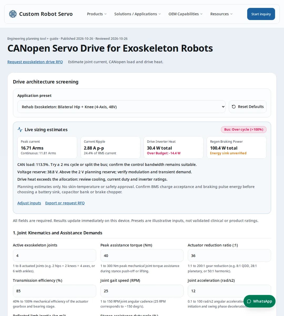
To reproduce default baseline: 4 active joints, 1000 kbps, 1.0 ms cycle, single_bus; modeled wire time 1,135 us, motor peak current 16.71 Arms, drive heat 27.7 W.
14. Engineering and RFQ questions
Actuator Sizing and Biomechanics
How do you size peak vs continuous torque for exoskeleton joint actuators?
Exoskeleton joint demands are highly cyclical. Peak torque occurs during stance push-off (for hips/ankles) or early stance weight acceptance (for knees), lasting 100–300 ms per step. Continuous (RMS) torque is calculated by integrating joint torque squared over the entire gait period (typically 35–45% effective stance duty). Sizing requires the motor drive to sustain continuous RMS current thermally without derating, while providing sufficient inverter silicon margin to deliver 2.0x to 3.0x peak torque during acceleration or stair climbing.
What gearhead reduction ratio is optimal: QDD (6:1–10:1) vs high-ratio planetary or cycloidal (30:1–80:1)?
Quasi-Direct Drive (QDD, 6:1 to 10:1) provides superior mechanical backdrivability, low passive impedance (reflected inertia scales with N^2), and transparent swing-phase motion without active force sensors. However, QDD demands larger, heavier frameless motors with high peak current. Planetary or cycloidal reducers (20:1 to 50:1) allow smaller, lighter motors to achieve high assistance torque (40–100 Nm), but introduce friction, backlash, and high reflected inertia requiring active torque feedback loops to cancel user-felt drag.
How does motor-reflected inertia impact exoskeleton wearer comfort and transparency?
The reflected inertia felt at the joint is J_reflected = J_motor * N^2 + J_gear. In high-ratio systems (e.g. 50:1), a small motor rotor inertia of 0.00008 kg*m^2 becomes 0.20 kg*m^2 at the joint, which feels heavy and resistive during unassisted human limb acceleration. For wearable exoskeletons, minimizing motor rotor inertia and selecting moderate gear ratios (10:1 to 30:1) preserves natural gait cadence and reduces the control bandwidth needed for active zero-torque impedance compensation.
How does joint assistance torque scale between medical rehabilitation and industrial load-assist?
Medical rehabilitation exoskeletons for paraplegic or stroke gait therapy typically deliver 30–60 Nm at the knee and hip to provide full or major bodyweight support at slow walking speeds (15–25 RPM). Industrial back-assist exoskeletons provide 40–80 Nm peak lumbar extension torque during static or repetitive lifting postures. Heavy-duty military or logistics exoskeletons support load carrying with up to 70–120 Nm peak torque per hip/knee joint.
How do you handle torque transitions across gait phases (stance vs swing)?
During stance phase (0–60% gait cycle), the drive operates in positive torque assistance to support body mass and propel forward motion. At toe-off and early swing (60–85%), the joint must rapidly transition to high transparency (near-zero resistance) or assist limb flexion. At terminal swing (85–100%), the knee actuator must exert negative braking torque to decelerate the lower leg before heel strike. Fast CST torque loop response (< 1.0 ms) is essential to eliminate resistance lag.
CANopen Bus Timing and CiA 402 Protocol
Why is Cyclic Synchronous Torque (CST) preferred over CSP in wearable exoskeletons?
Cyclic Synchronous Position (CSP) forces the robot joint along a rigid geometric trajectory, which can fight the user involuntary movements, muscle spasms, or natural stride variations, risking joint injury. Cyclic Synchronous Torque (CST) allows the central gait controller to inject a compliance torque profile (impedance or admittance control) based on ground reaction force, EMG, or joint angle sensors, ensuring the exoskeleton cooperates with rather than overpowers the human wearer.
What is the CAN bus wire time for a 4-axis bilateral exoskeleton at 1 Mbps?
At 1 Mbps, each bit time is 1.0 microsecond. An 11-bit CAN frame with 8 payload bytes requires approximately 135 bit times including bit stuffing allowance and interframe space. A zero-byte SYNC frame requires ~55 bit times. For 4 axes with 1 RPDO (target torque) and 1 TPDO (actual torque and position) per axis, total cyclic wire time is 55 + (4 * 2 * 135) = 1,135 microseconds (1.135 ms). At a 2.0 ms sync cycle, bus load is 56.8%, well within the recommended 60% cyclic limit.
How can you achieve a 1.0 kHz (1.0 ms) update rate on a 4-axis or 6-axis exoskeleton?
For 4 axes, a 1.0 ms cycle on a single bus results in ~113.5% theoretical wire load, which exceeds bus capacity. Two proven architectural solutions exist: (1) Dual-channel CAN split (left leg axes on CAN1, right leg on CAN2), reducing busiest bus wire time to 55 + (2 * 2 * 135) = 595 microseconds (59.5% bus load at 1.0 ms); or (2) Concentrated dual-axis drives that pack 2 axes target torques into 1 RPDO and 2 axes feedback into 1 TPDO, cutting total frame count by half.
How does CANopen message jitter affect exoskeleton control stability?
Human neuromuscular reflex loops have response latencies of 30–50 ms, but impedance control stability at the drive level requires low jitter (< 100 microseconds). CiA 301 SYNC frames sent with high priority (CAN ID 0x080) ensure all joint drives sample feedback and update inverter PWM duty cycles synchronously, preventing inter-joint phase lag that could cause gait asymmetry or torque ripple.
When should an exoskeleton design migrate from CANopen to CAN-FD or EtherCAT?
Classic CANopen (1 Mbps, 8-byte payload) is ideal for 2 to 6 axes where wiring simplicity, low power consumption (< 0.5 W per transceiver), and compact micro-connectors are critical. If the exoskeleton incorporates high-density tactile foot arrays, IMU sensor fusion on the same bus, or requires > 8 axes with 1 kHz CST updates, CAN-FD (up to 5 Mbps, 64-byte payload) or EtherCAT (100 Mbps) becomes advantageous despite higher cabling complexity and Ethernet PHY power dissipation.
What CiA 402 object dictionary entries govern real-time Cyclic Synchronous Torque (CST)?
In CST mode (object 0x6060 = 10), the supervisory gait controller writes target torque to 0x6071 (16-bit integer, scaled in 0.1% or per-thousand of rated motor torque 0x6076). Object 0x6072 sets the instantaneous peak torque clamp, and object 0x60B2 provides torque feedforward (offset) to dynamically inject model-based gravity and inertia compensation. Real-time feedback from the drive includes 0x6077 (actual torque) and 0x6064 (actual position). Statusword 0x6041 bit 10 confirms target tracking within configured error bands.
Why is split termination recommended for CANopen wiring in wearable exoskeletons?
Wearable exoskeletons route CAN bus differential lines in close proximity to motor phase leads switching up to 30 A at 32–50 kHz PWM. Standard single 120-ohm resistor termination leaves the bus susceptible to high-frequency common-mode EMI. Split termination uses two 60-ohm resistors in series at each bus end, with a 4.7 nF capacitor connecting the center tap to chassis ground. This creates a low-impedance path to shunt high-frequency common-mode noise while preserving 120-ohm differential bus termination.
Power, Battery and Regenerative Braking
Why is 48 V DC bus standard for wearable exoskeletons compared to 24 V?
A 48 V DC bus halves the motor phase and battery harness current compared to 24 V for the same joint mechanical power output (e.g. 250 W peak per joint). Lower current reduces I^2*R resistive losses by 75% in wearable battery wiring and MOSFET inverters, allowing thinner, more flexible cables through joint pivots and significantly reducing casing temperature rise.
How much regenerative braking power is generated during exoskeleton walking and descent?
During level walking terminal swing, the knee joint absorbs kinetic energy to decelerate the lower leg, generating 15–40 W of peak regenerative electrical power per leg for 80–150 ms. During stair descent or slope walking, the knee absorbs substantial body potential energy, producing 80–180 W peak electrical regen power. The drive must handle this reverse energy flow without tripping overvoltage.
Can the wearable lithium battery absorb regenerative braking energy safely?
Standard wearable lithium-ion battery packs have limited instantaneous charge acceptance rates (typically 0.5C to 1C continuous, 2C peak). Furthermore, if the battery is fully charged (100% SoC) or cold, the battery management system (BMS) may open protection FETs to prevent overcharging. If the BMS disconnects while the motor is regenerating, the drive DC bus voltage will spike instantly unless an active dynamic braking chopper with a compact clamp resistor is integrated.
How do you calculate battery peak current demand during two-legged stance push-off?
During simultaneous hip extension and ankle push-off, electrical input power equals mechanical power divided by drive and motor efficiency: P_elec = (T_joint * omega_joint) / (eta_mech * eta_drive). For two 60 Nm joints operating at 30 RPM (3.14 rad/s) with 80% combined efficiency, mechanical power is 377 W and DC electrical power is ~471 W. On a 48 V battery, peak current draw is ~9.8 A; on 24 V, it reaches ~19.6 A.
What is the impact of low-inductance frameless BLDC motors on current ripple and battery ripple stress?
Frameless torque motors often feature low phase inductance (50 to 150 microhenries) due to large pole counts and compact air gaps. At standard 20 kHz PWM and 48 V, current ripple can exceed 2.0 A peak-to-peak, generating unnecessary motor iron losses, acoustic noise, and DC link capacitor ripple heating. Using 32 kHz to 50 kHz PWM switching frequencies cuts ripple substantially without severe switching loss penalties in modern GaN or low-Qg silicon MOSFET stages.
Why do local DC bus capacitors fail to protect against regenerative overvoltage during stair descent?
A typical drive capacitor bank (e.g. 680 uF) stores only Delta E = 0.5 * C * (V_max^2 - V_nom^2) = 0.5 * 680e-6 * (56^2 - 48^2) = 0.28 Joules between nominal 48 V and 56 V maximum. During a 150 ms knee swing deceleration or stair descent step returning 50 W, total regenerative energy is 7.5 Joules—over 26 times the capacitor storage capacity! If the wearable battery BMS disconnects, this energy will push bus voltage above 150 V within milliseconds, destroying 60 V MOSFETs. An active braking chopper with external clamp resistor is indispensable.
Thermal, Safety and Medical Compliance
What are the surface temperature limits for wearable exoskeletons under IEC 60601-1 and ISO 13482?
IEC 60601-1 specifies that applied parts in continuous contact with human skin must not exceed 43 deg C for metal or 48 deg C for molded plastics. ISO 13482 requires similar risk controls for personal care robots. Because servo drives in exoskeletons are mounted directly on hip or thigh braces adjacent to human tissue, the drive housing must be thermally isolated from the wearer cuff, and heat must be directed outward into structural aluminum struts or convective airflow.
How is Safe Torque Off (STO) implemented in wearable exoskeleton servo drives?
Hardware Safe Torque Off (STO) per IEC 61800-5-2 provides dual-channel hardware isolation that disables gate driver power and pulls low-side and high-side MOSFET gates to ground independently of microcontroller firmware. When an emergency stop button or tether is pulled, STO cuts motor torque generation within < 5 ms, allowing the patient or worker to move freely without motor fighting, while maintaining encoder feedback over CANopen.
Why is dual-encoder architecture critical for exoskeleton joint safety?
A motor-side high-resolution magnetic encoder (e.g. 17-bit to 20-bit) provides smooth FOC current commutation and velocity estimation. A second absolute encoder mounted directly on the joint output side monitors the true anatomical joint angle. By cross-comparing both encoders, the drive and supervisor detect gearhead failure, mechanical decoupling, or torque windup, instantly enforcing electronic end-stops before the joint can exceed human biological range of motion (e.g. knee hyperextension beyond 0 deg).
How do you separate drive electronics heat from motor winding heat in wearable thermal design?
In an integrated exoskeleton actuator, motor copper and iron losses often generate 20–50 W of heat during strenuous walking, while the servo drive electronics generate 4–12 W. Conducting motor heat directly into the drive PCB can cause microcontroller shutdown and premature capacitor failure. An internal thermal break (e.g. ceramic/peek standoffs or air gap) between the stator casing and the drive inverter PCB protects sensitive drive electronics.
What EMC shielding and cable routing precautions are required for wearable CANopen lines?
Wearable exoskeletons route CAN bus lines alongside high-current motor phase leads (switched at 32 kHz PWM with fast dV/dt) through articulating hip and knee joints. To prevent communication frame corruption and bit errors, motor phase leads must be twisted and shielded, and CANopen signals (CAN_H, CAN_L) must use twisted-pair shielded cabling with 120-ohm terminations at bus endpoints. Common-mode chokes at drive CAN transceivers provide noise immunity.
What is the regulatory difference between ISO 13482, ASTM F48, and FDA Class II (PHH) for exoskeletons?
ISO 13482:2014 covers personal care and industrial physical assistant robots but explicitly excludes clinical medical devices. Occupational industrial exoskeletons follow ASTM Committee F48 standards (e.g. ASTM F3474 for ergonomics and F3578 for stumbling risk). In contrast, therapeutic gait rehabilitation exoskeletons for neurological rehabilitation are regulated as medical devices (U.S. FDA 510(k) under Product Code PHH, 21 CFR 890.3480), requiring compliance with IEC 60601-1, IEC 60601-1-2, and software lifecycle verification under IEC 62304 Class B/C.
How do you size exoskeleton brace cuffs to prevent skin pressure injuries under ISO/TS 15066 limits?
ISO/TS 15066 establishes quasi-static pressure pain thresholds of 210 kPa for the anterior thigh and 220 kPa for the lower leg/shin. For medical comfort and to avoid circulatory occlusion (capillary closing pressure ~4.3 kPa), continuous contact pressure should remain below 15–20 kPa. For a 60 Nm joint assist with a 0.25 m lever arm (240 N cuff force), minimum padded cuff contact area must exceed A = 240 N / 20,000 Pa = 120 cm^2 (e.g., 10 cm x 12 cm cuff strap with breathable memory foam padding).