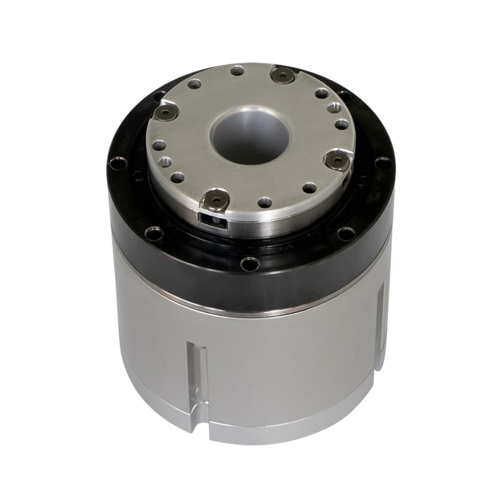
Unboxing the Backlash Blackbox: Harmonic vs Cycloidal vs Planetary for Robotic Joints
A deep engineering guide to choosing between Harmonic, Cycloidal, and Planetary reducers for custom robotic joints to manage backlash, rigidity, and shock loads.
Executive Summary (TL;DR)
- Zero-backlash is a myth; engineers must define the acceptable arcmin tolerance based on the robot's kinematic chain and end-effector precision requirements.
- Strain wave (harmonic) gearing offers compact high-ratio reduction but suffers from low torsional stiffness compared to cycloidal drives.
- Cycloidal reducers provide extreme impact resistance and stiffness, making them ideal for base joints, though they carry a weight penalty.
- Dual-encoder architectures can digitally compensate for transmission error and hysteresis in all reducer types.
The Backlash Blackbox
For an integrated robotic joint, the gear reducer is the most critical architectural decision. It dictates the entire system's rigidity, precision, weight, and shock resistance. Selecting the wrong reducer type dooms the robot's performance, regardless of how perfectly the servo motor and drive are matched.
A major pain point in procurement is what we call the "Backlash Blackbox." Many standard catalogs publish an isolated backlash figure (e.g., < 3 arcmin) without revealing the test conditions.
- Was it measured under zero load or 20% load?
- What was the reversal testing methodology?
- Did they account for hysteresis and lost motion, or just pure gear mesh clearance?
When building custom robot servos, we open the blackbox. We align the reducer selection strictly with your application's physical realities. To understand thermal limitations that may compound these issues, see our guide on Thermal Derating Physics in Robot Servos.
Operating Principles: Visualizing the Mechanics
Before comparing metrics, it's essential to understand the physical mechanisms driving each topology.
Comprehensive Reducer Comparison
To make objective engineering decisions, we must evaluate the big three across physical and performance metrics.
| Metric | Harmonic (Strain Wave) | Cycloidal | Planetary |
|---|---|---|---|
| Backlash (arcmin) | < 1 (Often near-zero) | 1 - 3 | 3 - 10+ (Standard) |
| Torsional Stiffness (Nm/arcmin) | Moderate (Non-linear curve) | Extremely High | High |
| Shock Rating (% of nominal) | 200% (Vulnerable to ratcheting) | 500% (Indestructible in normal use) | 300% |
| Weight (relative) | Lightweight | Heavy / Dense | Moderate |
| Efficiency (%) | 60 - 75% | 75 - 85% | 90 - 95% |
| Ratio Range (Single Stage) | 30:1 to 160:1 | 10:1 to 120:1 | 3:1 to 10:1 |
| Axial Length (relative) | Very Short (Pancake) | Short / Moderate | Long (Requires stacking) |
| Backdrivability | Fair (Easier at lower ratios) | Poor (Due to sliding friction) | Excellent |
| Noise | Very Low | Low to Moderate | Moderate to High |
| Cost (relative) | High | Very High | Low to Moderate |
| Lifetime (cycles/hours) | 5,000 - 10,000 hours | 20,000+ hours | 10,000 - 20,000 hours |
Stiffness vs. Backlash: Understanding the Hysteresis Loop
Many engineers mistakenly fixate entirely on "backlash" (pure gear mesh clearance) while ignoring torsional stiffness and hysteresis. In a robotic arm extended to 1 meter, low torsional stiffness can cause millimeters of sag, even if the gear mesh backlash is physically zero.
Lost motion (or hysteresis) represents the total wind-up and internal deflection of the gear system when torque is applied and then reversed. Harmonic drives, due to the intentional flexing of the flexspline, exhibit a non-linear stiffness curve. At low torques, stiffness is low (lost motion is high).
When specifying your joint, a cycloidal drive will often have higher initial backlash, but a much steeper (stiffer) torsion curve, making it superior for heavy lifting where dynamic deflection is the true enemy.
Application Decision Matrix
Where should you use which reducer? Here is our internal mapping for integrated robot joints.
| Application / Joint | Recommended Reducer | Reasoning |
|---|---|---|
| Humanoid Shoulder / Elbow / Wrist | Harmonic | Ultra-compact axial form, lowest weight for upper-body agility, excellent ratio to mass. |
| Humanoid Hip / Knee / Ankle | Cycloidal | Impact from walking/running requires 500% shock rating. High stiffness prevents leg buckling under dynamic loads. |
| Cobot J1 - J6 (Base to Wrist) | Harmonic | Prioritizes absolute precision, compactness, and zero-backlash for collaborative tasks and teaching. |
| Industrial Scara / Base Joint (J1) | Cycloidal | Needs massive rigidity to handle the inertia of the extended arm swinging at high speeds. |
| AGV / AMR Steering & Drive | Planetary | Cost-effective, handles high speeds, excellent efficiency for battery life. Precision is handled by external odometry. |
| Robotic Gripper Actuation | Planetary or Micro-Harmonic | Space constraints dictate micro-planetaries, but high-end CNC tending grippers may use micro-harmonics for zero-play holding. |
Digital Compensation: The Dual Encoder Advantage
Even the best harmonic or cycloidal reducer will deflect under load. To achieve true zero-error positioning at the end-effector, modern integrated servos utilize a Dual Encoder Architecture.
By placing a high-speed incremental encoder on the motor shaft (before the reducer) and a high-resolution absolute encoder on the output shaft (after the reducer), the servo drive's control loop can digitally measure and eliminate transmission error, backlash, and hysteresis in real-time.
To see how we integrate these into a finished package, check out our Integrated Robot Servos.
Failure Mode Analysis
Understanding how a reducer fails helps you design safer robots.
| Reducer Type | Common Failure Mode | Primary Cause | Symptom | Prevention |
|---|---|---|---|---|
| Harmonic | Flexspline Ratcheting / Fracture | E-Stop shock loads, hitting environmental obstacles at speed. | Sudden total loss of joint holding torque. | Implement slip clutches, software torque limiting, or switch to cycloidal for legs. |
| Harmonic | Wave Generator Bearing Wear | Continuous high-speed operation overheating the grease. | Increasing acoustic noise, increased lost motion. | Strictly adhere to duty-cycle limits and thermal derating. |
| Cycloidal | Pin/Lobe Galling | Lack of proper grease film under extreme radial loads. | Grinding noise, increased running friction (overheating). | Regular grease replacement, specify correct EP (Extreme Pressure) lubricants. |
| Planetary | Sun Gear Shearing | High-inertia load reversals. | Freewheeling output. | Upsize the gearbox, soften acceleration profiles. |
Lifetime and Lubrication
Reducer life is predominantly dictated by bearing L10 life and lubricant degradation. Harmonic drives typically specify a 5,000 to 10,000-hour L10 life under nominal loads. However, grease breakdown accelerates dramatically with temperature.
Operating a reducer above 70°C can halve the grease's effective lifespan. Specialized harmonic greases (like Harmonic Drive's SK-1A or 4B No.2) must be selected based on the operating orientation (vertical vs. horizontal) to prevent leakage and ensure the wave generator bearing remains immersed. Re-lubrication intervals should be strictly scheduled every 2,000-3,000 hours for heavily utilized industrial robots.
RFQ Specification Template
When you submit an RFQ for an integrated smart servo or robotic joint actuator, don't just ask for "a 100:1 reducer with low backlash." To get an actuator that actually survives field testing, provide the following checklist. (For more details, see our Custom Robot Servo RFQ Guide).
| Parameter to Specify | Why It Matters for the Reducer |
|---|---|
| Continuous RMS Torque (Nm) | Dictates the base size of the reducer to prevent thermal and fatigue failure. |
| Peak/E-Stop Shock Load (Nm) | Determines if a Harmonic drive will shatter. Forces transition to Cycloidal if too high. |
| Max Output Speed (RPM) | Affects input motor speed and potential overheating of reducer bearings. |
| Torsional Stiffness (Nm/arcmin) | Ensures the robot's end-effector doesn't sag unacceptably under payload. |
| Moment / Overhung Load (Nm) | Cross-roller bearing sizing. Can the reducer support the physical arm weight directly? |
| Backlash Tolerance (arcmin) | Determines required manufacturing precision and whether dual-encoders are necessary. |
| Target Weight (kg) | Forces trade-offs between rigidity and mass (Cycloidal vs Harmonic). |
Stop Guessing, Start Engineering
Our engineering team will help you navigate the tradeoffs between harmonic precision and cycloidal durability. We integrate high-resolution dual encoders to digitally compensate for mechanical deflection and hysteresis, ensuring your custom actuator behaves exactly as your kinematics solver expects.
Inquiry Email
Include drawings, torque/speed, protocol, and prototype quantity.
Author

Categories
More Posts
The Hidden Costs in Custom Robot Servo OEM Manufacturing
A transparent breakdown of tooling, NRE, PCBA, and supply chain costs when scaling custom robotic joints from prototype to mass production.
BLDC vs PMSM for Custom Robot Servos: Which Motor Architecture Wins?
An engineering comparison between Brushless DC (BLDC) and Permanent Magnet Synchronous Motors (PMSM) for high-performance robotics actuation.
EtherCAT vs CANopen for Multi-Axis Robotic Actuation
Analyzing the real-world latency, synchronization, and cost trade-offs of EtherCAT versus CANopen in custom multi-axis servo drives.