Dual-Encoder Robot Joint Servos: Sizing and Tuning Guide
Size dual-encoder robot joint servos, compare feedback architectures, and plan resonance tuning. Use the engineering checklist to prepare an actuator RFQ.
Executive Summary (TL;DR)
- Dual-encoder robot joint servos measure both motor and output angle, allowing feedback to reduce transmission-related positioning error within the available torque and control bandwidth.
- Motor feedback supports commutation and velocity control; output feedback closes the position loop. Adding output feedback without retuning can excite elastic modes.
- Encoder resolution is not installed accuracy. Specify an output-angle error budget, calibrated mounting, payload range, and measured stability margins.
- Dual feedback does not remove physical compliance, guarantee collision-free startup, or provide a certified safety function. Numerical examples below are calculations, not measured product results.
For engineering and procurement teams specifying a custom robot servo, a high-resolution motor encoder does not establish accuracy at the robot's tool-center point (TCP). A geared joint can report a small motor-position error while the output link deflects under payload or drifts over temperature.
Possible contributors include encoder installation error as well as gear elasticity, tooth backlash, flexspline hysteresis, bearing deflection, and thermal expansion across the joint structure.
Dual-encoder feedback architecture makes transmission-related output error observable. However, adding a second encoder without reviewing loop gains, delay, and mechanical modes can introduce two-mass resonance instability and hunting.
This guide breaks down the physical mechanics of dual-encoder systems, the control loop mathematics required to prevent oscillation, hollow-shaft mechatronic packaging tolerances, and the essential engineering parameters required when sourcing or customizing dual-feedback robot servos.
Scope and review date — 26 October 2026: English-language guidance for global OEM buyers of geared electric robot joints. The equations use a simplified linear, single-axis model. Examples are illustrative assumptions, not supplier ratings or lab measurements. Feedback can reduce error at the encoder plane; it cannot remove gearbox elasticity, unmeasured link bending, or bearing tilt. Confirm all limits against the selected reducer, encoder, drive firmware, and application test plan.
Preparing a specification? Send your joint envelope, load case, and accuracy target for an RFQ review.
The Illusion of Motor-Side Precision
In a conventional servo joint, a single rotary encoder is coupled directly to the high-speed motor rotor. With a 19-bit absolute encoder and a 100:1 strain wave or cycloidal gearbox, calculate the equivalent output step as follows:
Equivalent output counts/rev = 2^19 × 100 = 52,428,800
Equivalent output step = 1,296,000 arcsec / 52,428,800 ≈ 0.0247 arcsec
This is a quantization calculation, not an accuracy or repeatability claim. It also assumes motor turns are tracked: a single-turn motor encoder repeats every rotor revolution and cannot uniquely identify output position through a reducer after power loss. Four mechanical effects further separate motor position from actual link position:
- Backlash and Lost Motion: A reducer marketed as zero-backlash can still exhibit hysteresis and load-dependent lost motion. Request the selected model's bidirectional torque-angle curve and test conditions rather than assigning a universal backlash value.
- Torsional Elasticity (
K_gear): Under payload or acceleration, the transmission behaves approximately as a torsional spring. For an assumed output-referenced stiffness of 18,000 Nm/rad and a 40 Nm load,Δθ = torque / stiffness = 40 / 18,000 = 0.00222 rad ≈ 7.64 arcmin. At an 800 mm reach, the small-angle estimateTCP displacement ≈ reach × Δθgives 1.78 mm. This output deflection is not directly measured by the motor encoder. - Structural and Cross-Roller Bearing Tilt: External radial and moment loads tilt the output cross-roller bearing, shifting the true kinematic axis relative to the stator.
- Thermal Expansion: Motor heat changes housing, gearing, bearing, and sensor geometry. Differential expansion can alter zero-point calibration over the duty cycle; its magnitude depends on materials and the assembled temperature field.
+-----------------------------------------------------------------------------------+
|                           THE MECHANICAL DEFLECTION GAP                           |
+-----------------------------------------------------------------------------------+
|  [Motor Rotor] ---> [Motor Encoder]                                               |
|       |                                                                           |
|       v (Reported position: 0.000° error)                                         |
|  [Flexible Reducer / Gear Teeth] <--- Backlash + Elastic Twist + Thermal Growth   |
|       |                                                                           |
|       v (Illustrative output deflection: -0.127° under 40 Nm load)               |
|  [Output Link] ---> [Tool Center Point Deflects 1.78 mm]                          |
+-----------------------------------------------------------------------------------+
To observe this deflection gap, mount a secondary, load-side encoder directly to the output flange. The controller can then compensate for some transmission error and elastic windup within its torque, travel, and bandwidth limits. HEIDENHAIN's position-measurement note, page 5 explains why measuring a rotary axis directly exposes errors hidden by motor-only feedback.
However, closing a position loop across an elastic transmission is mathematically non-trivial.
For the mechanical selection behind this model, see the robot-joint backlash and reducer selection guide.
The Physics of Joint Compliance: Two-Mass Resonance and the "Hunting" Trap
One possible failure mode when retrofitting load feedback is limit-cycle oscillation, often called hunting or chatter. It is a tuning risk, not an inevitable consequence of output sensing.
An actuator with motor inertia J_M, transmission torsional stiffness K_gear, and load inertia J_L can be approximated as a two-mass resonant mechanical system. Here all mechanical quantities are referred to the output shaft: for reduction ratio N = motor speed / output speed, the motor's equivalent inertia is J_M × N².
The system possesses two distinct characteristic frequencies:
1. Anti-Resonance Frequency (f_ar)
For the undamped model, the motor-angle response to applied motor torque has a zero at the anti-resonance frequency:
f_ar = sqrt(K_gear / J_L) / (2π)At f_ar, motor motion is suppressed while the load may still oscillate. This is a notch in the motor response, not a frequency at which the load necessarily stops moving. Damping and nonlinear friction soften the ideal notch.
2. Resonance Frequency (f_r)
The resonance frequency is the natural frequency of the combined motor and load oscillating against each other out of phase:
f_r = sqrt(K_gear × (1 / (J_M × N²) + 1 / J_L)) / (2π)
    = f_ar × sqrt(1 + J_L / (J_M × N²))
Where:
K_gearis output-referenced reducer stiffness in Nm/rad.J_Lis load inertia at the joint output in kg·m², including link and tool.J_Mis physical motor rotor inertia in kg·m² before output-side reflection.Nis the dimensionless reduction ratio, such as 80 or 100.
For assumed values K_gear = 18,000 Nm/rad, J_L = 0.25 kg·m², J_M = 0.00004 kg·m², and N = 80, these equations give f_ar ≈ 42.7 Hz and f_r ≈ 60.0 Hz. These are model estimates; identify the installed response across the payload and pose range before tuning.
Why Moving Feedback Without Retuning Can Cause Hunting
Replacing motor feedback with load feedback changes the plant seen by the controller:
- Flexible modes and sensor delay alter phase and gain near crossover. The exact phase response depends on the feedback location and damping.
- An aggressive velocity controller may demand torque before the load responds through the elastic reducer.
- Integral action can wind up against torque saturation unless anti-windup is configured.
- Backlash, friction, and torque reversals can sustain a limit cycle even when a linear model appears stable.
Hunting can heat the motor and increase gear wear. Separate motor-based damping from load-position correction, then validate the complete closed-loop response.
Cascaded Dual-Loop Control Architecture
A cascaded dual-loop control architecture assigns commutation and velocity to the motor encoder and position to the output encoder, as described in Synapticon's dual-loop guide. When evaluating CANopen servo drives for cobot joints, request explicit confirmation of two feedback interfaces and firmware support; fieldbus support alone does not establish dual-loop capability.
The diagram is conceptual and omits the motor/reducer plant between current command and measured motion. Its rates are illustrative update rates, not control bandwidths or product specifications. PWM frequency, current sampling, encoder data rate, and closed-loop bandwidth are separate quantities.
Functional Allocation Across Loops
- Current / Commutation Loop (illustrative 16 to 32 kHz update):
- Uses measured phase currents and motor electrical angle for FOC. Correct commutation calibration remains necessary.
- Inner Velocity Loop (illustrative 8 to 16 kHz update):
- Uses motor-derived velocity for damping. Excessive gain can still excite the coupled mechanics.
- Resonance Filtering:
- Where supported, a second-order notch in the torque or velocity command path can attenuate a measured resonant peak. It does not cancel the physical mode across all payloads.
- Select notch depth, width, and any low-pass cutoff using the measured response and delay budget. A fixed multiple of anti-resonance frequency is not a universal tuning rule.
- Outer Position Loop (illustrative 1 to 2 kHz update):
- Uses load angle to correct position error within the slower loop's validated bandwidth. Start with conservative gains, then test reversals, settling, saturation recovery, and payload extremes.
Tune from the inner loops outward, with limited excitation amplitude and mechanical travel. Log both encoders, torque/current, tracking error, and frame errors. Verify stability and temperature at minimum and maximum load before accepting faster settling as a benefit.
Motor-Side vs. Load-Side Encoders: Architectural Matrix
When integrating dual encoders into an actuator envelope, the mechanical, electrical, and optical properties of each feedback node differ fundamentally.
| Architectural Dimension | Motor-Side Primary Feedback | Load-Side Secondary Feedback |
|---|---|---|
| Physical Mounting Location | High-speed rotor shaft (pre-reducer) | Joint output flange / link carrier (post-reducer) |
| Primary Motion Function | FOC commutation, electrical angle, velocity damping | Absolute link positioning, backlash compensation, kinematics |
| Sensing Technology | Magnetic, inductive, optical, or resolver feedback supported by the drive | Hollow-shaft optical, magnetic, or inductive encoder selected for installed accuracy |
| Resolution Selection | Check electrical-angle quantization at maximum rotor speed | Set angular step below the error budget; verify accuracy separately from bit count |
| Update Rate | Coordinate encoder updates with current and velocity control | Coordinate acquisition, position loop, and bus timing; rates are firmware-specific |
| Latency & Jitter Sensitivity | Budget sensor, transport, and computation delay against phase margin | Include timestamp alignment; slower motion does not make arbitrary delay acceptable |
| Mechanical Installation Tolerance | Follow the encoder's gap, alignment, and shaft-speed limits | Allocate eccentricity, runout, bearing motion, and calibration residuals to the angle budget |
| Vibration & Shock Exposure | Motor harmonics and rotor acceleration | Link vibration and external impact; qualify both against the application |
| Dominant Sourcing Risk | Temperature drift near motor winding heat sink | Cross-talk/EMI in shared hollow bore and bearing deflection |
Optical vs. Magnetic Off-Axis Rings: Packaging in Hollow Bores
In collaborative robot joints and humanoid actuators, space is constrained. Some applications require a hollow bore to route power harnesses, fieldbuses, pneumatics, or slip ring connections. Specify the required clear diameter through the complete assembly rather than assuming all joints provide the same bore.
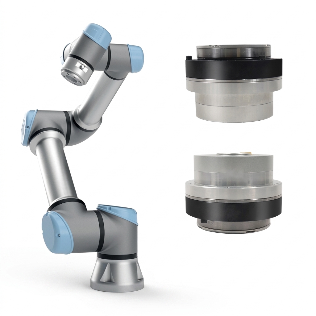
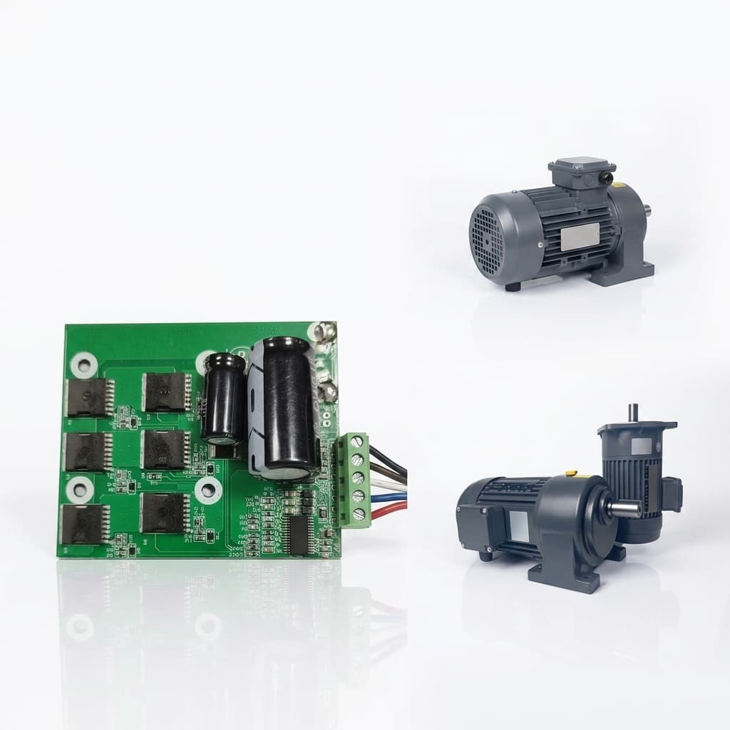
Product illustration: external joint packaging only; the photograph does not establish internal encoder count, bore clearance, or measured performance.
Selecting the sensor technology for the load-side encoder affects physical dimensions and assembly requirements:
1. Optical Hollow-Shaft Encoders
- Mechanism: A chrome-on-glass disc or code wheel rotating past an optical LED array with photo-detector ICs.
- Advantages: Precision angle measurement without direct magnetic-field sensitivity. Installed accuracy depends on scale quality, readhead geometry, and calibration.
- Disadvantages: Contamination, condensation, shock rating, sealing, and mounting gap require model-specific checks. Neither a universal shock limit nor a single ingress rating applies to every optical design.
2. Magnetic Off-Axis (Hall/AMR/GMR) Encoders
- Mechanism: A multi-pole magnetized ring (alternating north/south pole pairs along the perimeter) paired with an interpolation sensor IC.
- Advantages: Can support compact packaging and tolerate some nonmagnetic contamination. Verify shock, temperature, chemical exposure, and air-gap ratings for the selected assembly.
- Disadvantages: Stray fields from the motor or brake and ferromagnetic debris can affect readings. Evaluate shielding and any lookup-table calibration against the sensor manufacturer's field limits.
The Mechanical Runout Trap (TIR)
For a single-readhead ring, eccentricity can be a significant contributor to cyclic angle error. Distinguish center offset e from radial Total Indicator Reading (TIR): for a round ring with pure eccentricity, TIR ≈ 2e.
For an illustrative 50 mm diameter ring with 25 µm radial TIR, e ≈ 12.5 µm and radius R = 25,000 µm. A first-order geometric estimate is:
Peak angle error ≈ e / R = 12.5 / 25,000 = 0.0005 rad ≈ 1.72 arcminThis estimate is not a calibration model for every magnetic encoder; multiple readheads and signal processing can change eccentricity sensitivity. Allocate an installation-error budget and request an installed angle-error map. Discuss housing datums, bearing seats, and inspection methods during servo drawing-to-production planning; a particular CNC axis count alone does not establish accuracy.
High-Speed Serial Protocols: Shielding BiSS-C Against Inverter PWM Noise
In an integrated actuator, the load-side encoder PCB is positioned at the extreme end of the output shaft, while the servo drive inverter PCB is located at the base or wrapped concentrically around the motor.
Encoder lines may share a constrained route with switched motor-phase conductors. Record the actual DC bus voltage, PWM settings, cable lengths, and edge rates when qualifying the harness; none of these values can be inferred from encoder bit count.
Capacitive and inductive coupling can corrupt serial position packets. A correctly configured drive should reject invalid data; frame errors, stale feedback, and recovery behavior still need to be checked during qualification.
Protocol Comparison: BiSS-C vs. SSI vs. EnDat 2.2
| Parameter | BiSS-C (Open Standard) | SSI (Synchronous Serial) | EnDat 2.2 (Proprietary) |
|---|---|---|---|
| Transmission Type | Bidirectional synchronous serial | Unidirectional point-to-point | Bidirectional synchronous |
| Clock Selection | Match encoder/master clock and cable-delay limits | Match sensor clock and timeout requirements | Match encoder and master specifications |
| Data Integrity Verification | Profile-defined CRC; configure polynomial and word length | Parity, status bits, or no integrity check, depending on device | Verify supported CRC and diagnostic handling in both devices |
| Latency per Request | Include latch time, processing, clocked bits, propagation, and timeout | Include word length, clock rate, and timeout | Use the selected encoder's timing specification |
| Multi-Turn Retention | Encoder hardware determines retention, not the protocol alone | Encoder-dependent | Encoder hardware determines retention, not the protocol alone |
| Integration Check | Verify frame layout, error flags, and control-channel support | Verify data format, parity, and update timing | Verify interface version and supported commands |
Sourcing & Hardware Noise Isolation Rules
The BiSS Association's interface description explains latch timing, line-delay compensation, CRC configuration, and timeout. Use those features alongside the selected encoder's electrical specification; the interface name does not guarantee zero dropped frames.
- Differential Signaling: For RS-422 BiSS-C devices, route clock and data as their specified differential pairs with the required termination and receiver levels. Avoid long exposed single-ended segments near phase wiring.
- Harnessing and Bonding: Use the specified twisted pairs, shielding, separation, and chassis bonds. Validate the assembled routing and grounding arrangement rather than mandating one sleeve or shield topology for every joint.
- Fault Handling: Reject invalid frames and define stale-data age, consecutive-error limits, diagnostics, and the response to lost feedback. Any hold or prediction must have a validated time limit. Do not prescribe a universal one-cycle hold or assume an immediate torque-off is safe for a gravity-loaded joint.
CiA 402 Implementation: Mapping Dual Feedback in EtherCAT & CANopen
Many CANopen and EtherCAT motion drives use the CiA 402 device profile. CAN in Automation's profile overview explains standardized behavior and PDOs, while also noting differences in optional vendor functions. CiA 402 compliance alone does not specify which physical encoder closes each loop.
+-----------------------------------------------------------------------------------+
|                   EXAMPLE DUAL-FEEDBACK ROUTING — VERIFY PER DRIVE                 |
+-----------------------------------------------------------------------------------+
|                                                                                   |
|  [Selected Position Encoder] ----> Object 6064h (Position Actual Value)             |
|                                     - Confirm source, scaling, and PDO mapping    |
|                                                                                   |
|  [Motor-Side Rotor Encoder]  ----> Internal commutation / velocity control           |
|                                     - Diagnostics use drive-specific objects     |
|                                                                                   |
|  [Scaled Motor / Load Difference] -> Vendor-specific diagnostic, if available       |
|                                     - Not automatically a safety function        |
|                                                                                   |
+-----------------------------------------------------------------------------------+
Key Object Configuration Strategy
- Position actual value (
6064h): Confirm the selected encoder, sign, units, offsets, and rollover behavior in the drive manual and EDS/ESI. Check the master sees the intended load angle using a limited-motion commissioning test. - Motor feedback diagnostics: Request the documented objects for motor position, velocity, and status. Do not assume a standard internal-position object is a dedicated second-encoder channel.
- Transmission discrepancy: Where available, evaluate
Δθ_error = θ_load − θ_motor / N − calibrated offsetusing synchronized, consistently unwrapped angles. Set thresholds and persistence from normal elastic twist, calibration uncertainty, and payload transients. This diagnostic does not by itself establish safe gearbox-failure detection or a safe stop response.
Worked Sizing Example: A 10 kg Payload at 750 mm Reach
This is a hypothetical sizing worksheet, not a customer case study or lab test. Assume a horizontal single-axis lever, a 10 kg point payload, an 80:1 reducer, and 80% motoring efficiency for preliminary screening. Link weight, friction, acceleration, and thermal duty are excluded. The earlier 40 Nm stiffness example is a separate load case.
| Quantity | Method or assumption | Calculated value / interpretation |
|---|---|---|
| Payload moment | 10 kg × 9.81 m/s² × 0.75 m | 73.6 Nm at the joint output |
| Motor torque screen | 73.575 / (80 × 0.80) | 1.15 Nm; a rough motoring estimate, not a validated holding rating |
| Assumed baseline output error | 4.2 arcmin, selected for this example | A requirement input, not an observed droop |
| Corresponding TCP displacement | 0.75 × 4.2 × π / 10,800 | 0.000916 m ≈ 0.916 mm |
| Proposed residual-angle target | 0.18 arcmin | To be demonstrated by installed-axis tests |
| Corresponding TCP target | 0.75 × 0.18 × π / 10,800 | 0.0000393 m ≈ 0.039 mm from this joint alone |
| 20-bit output encoder step | 21,600 arcmin / 2^20 | 0.0206 arcmin per count; installed accuracy remains separate |
| Dynamic settling / throughput | Requires measured response and complete cycle timing | No settling-time or throughput improvement is inferred |
For a motor decision, add the full link/tool gravity moment, acceleration torque, reducer limits, and RMS duty. With a compatible torque-constant convention, motor current ≈ motor torque / K_t; the winding's continuous-current and peak-duration ratings must be checked separately. Reducer static friction and backdriving behavior mean the assumed efficiency cannot establish actual holding current.
For acceptance, define payload and pose range, temperature, supply voltage, motion profile, approach direction, angular-error window, settling dwell, and instrument uncertainty. Compare motor-only and dual-feedback configurations using an independent calibrated angle reference or suitable TCP metrology. Record raw traces; encoder agreement alone is not proof of TCP accuracy.
Engineering & Sourcing Checklist: What to Specify in a Dual-Encoder RFQ
When sourcing a custom robot servo or integrated joint actuator, sending an RFQ that simply requests "dual encoders" leaves critical technical decisions to the supplier's guesswork.
Use this checklist to ensure your mechanical, electrical, and validation parameters are locked into the contract:
- Dual Feedback Scope: Explicitly specify technologies for both channels (e.g., Primary: 18-bit magnetic on-axis for motor commutation; Secondary: 20-bit optical or shielded magnetic off-axis for load).
- Hollow-Bore Clearance: Define minimum clear inner diameter (ID) through the complete joint, accounting for cable sleeves and mechanical retention rings.
- Protocol & Physical Layer: Specify communication protocols (e.g., BiSS-C point-to-point or SSI), maximum clock frequency (e.g., 5 MHz or 10 MHz), and required differential transceiver line drivers.
- Mechanical Concentricity & Runout: Specify datums, radial TIR, axial runout, and readhead gap using the encoder mounting guide and the allocated installed-angle error budget.
- Drive Firmware Dual-Loop Support: Verify whether the servo drive supports cascaded dual-loop control natively, including independent loop frequency scaling and programmable bi-quad anti-resonance filters.
- Zero-Offset Non-Volatile Mastering: Require the supplier to calibrate and write the absolute zero alignment into the joint's onboard non-volatile memory during factory acceptance.
- Thermal Qualification: Define the motor duty cycle, ambient range, sensor temperature limit, warm-up state, and allowed zero drift; validate the assembled joint under load.
- Magnetic Shielding Provisions: Require field measurements at the sensor during peak current and brake switching; agree shielding only where needed to meet the selected sensor's limits.
- Factory Acceptance Test (FAT) Requirements: Agree a calibrated output-angle or TCP measurement method across the permitted travel in both directions, with payload, temperature, uncertainty, and raw-data records.
- Discrepancy and Fault Response: Agree motor/load discrepancy thresholds, frame-error handling, stopping behavior, brake coordination, and any separately required safety functions.
Include these inputs in your custom robot servo engineering inquiry, especially the distinction between encoder resolution and the installed output-accuracy acceptance limit.
Use the custom robot servo RFQ guide to organize drawings, validation evidence, and prototype-to-production requirements alongside this dual-feedback checklist.
Frequently Asked Questions (FAQ)
Can I run a dual-encoder joint actuator with a standard low-cost servo drive?
Check the exact model. You need two supported feedback channels, configurable assignment to commutation/velocity/position, sufficient timing performance, and a stable tuning strategy. Connector count, low price, or a CiA 402 label alone does not establish or exclude dual-loop support. A notch filter is one possible tuning tool, not a universal prerequisite.
Why not use an optical encoder for both motor and load sides?
You can use optical feedback on both sides if the selected devices meet speed, temperature, contamination, shock, and mounting requirements. Magnetic or inductive alternatives may simplify some packaging constraints. Compare installed accuracy and environmental ratings rather than treating one sensing technology as universally more reliable.
How does dual-encoder feedback affect robot homing and startup?
Dual feedback does not automatically provide retained multi-turn position. A single-turn absolute output encoder identifies angle within one revolution; restricted-travel axes may use that with validated mastering and range checks. Multi-turn axes need a suitable retained turn count or a referencing procedure. Verify zero offsets, battery or energy-harvesting behavior, and plausible state after power loss. Absolute feedback alone cannot guarantee collision-free restart.
Does a dual-encoder setup eliminate the need for a high-quality gearbox?
No. Feedback can reduce low-frequency position error but cannot remove physical compliance, friction variation, or lost-motion limits. Large deadbands may require lower gains, trajectory changes, feedforward, or mechanical improvement; a notch filter does not repair backlash. Select reducer stiffness and durability for the required loads and dynamics.
What causes position jumps when reading BiSS-C encoders near high-torque moves?
Possible causes include EMI, power dips, termination errors, incorrect clock or frame settings, mechanical sensor movement, and angle rollover handling. Correlate CRC/status flags, sensor supply measurements, both encoder traces, and the motion event. Apply the sensor and drive manufacturers' shielding and bonding instructions, then recheck the assembled joint under peak current.
Sources & Technical References
Sources checked on 26 October 2026. These references support the architecture and interface principles; they do not validate the illustrative numbers or certify a custom actuator.
- Synapticon — Dual-loop position control with two encoders: Motor/load feedback allocation and gear-ratio configuration. Product-specific implementation details apply to Synapticon devices.
- CAN in Automation — CiA 402 series: CANopen device profile for drives and motion control: Profile scope, IEC relationship, PDOs, and implementation differences. This overview is not a selected drive's object dictionary.
- BiSS Association — BiSS Interface: Latch timing, line-delay compensation, profile-defined data/CRC fields, and timeout behavior. Use the encoder datasheet for electrical limits.
- HEIDENHAIN — Influence of Position Measurement on Accuracy in 5-Axis Machining, page 5 (2011): Direct rotary-axis measurement versus motor-only feedback. This machine-tool note supports the measurement principle, not robot-specific performance numbers.
Start Your Custom Dual-Encoder Actuator Project
Designing a dual-encoder joint module requires coordination across motor winding, reducer integration, encoder mounting, machining, and servo drive firmware.
Send your CAD envelope, torque-speed and duty-cycle requirements, output-angle error budget, travel range, bus protocol, and prototype quantity. Ask our engineering team to confirm feedback support and propose an acceptance test before finalizing the actuator specification.
Inquiry Email
Include drawings, torque/speed, protocol, and prototype quantity.
Author

Categories
f_ar)2. Resonance Frequency (f_r)Why Moving Feedback Without Retuning Can Cause HuntingCascaded Dual-Loop Control ArchitectureFunctional Allocation Across LoopsMotor-Side vs. Load-Side Encoders: Architectural MatrixOptical vs. Magnetic Off-Axis Rings: Packaging in Hollow Bores1. Optical Hollow-Shaft Encoders2. Magnetic Off-Axis (Hall/AMR/GMR) EncodersThe Mechanical Runout Trap (TIR)High-Speed Serial Protocols: Shielding BiSS-C Against Inverter PWM NoiseProtocol Comparison: BiSS-C vs. SSI vs. EnDat 2.2Sourcing & Hardware Noise Isolation RulesCiA 402 Implementation: Mapping Dual Feedback in EtherCAT & CANopenKey Object Configuration StrategyWorked Sizing Example: A 10 kg Payload at 750 mm ReachEngineering & Sourcing Checklist: What to Specify in a Dual-Encoder RFQFrequently Asked Questions (FAQ)Can I run a dual-encoder joint actuator with a standard low-cost servo drive?Why not use an optical encoder for both motor and load sides?How does dual-encoder feedback affect robot homing and startup?Does a dual-encoder setup eliminate the need for a high-quality gearbox?What causes position jumps when reading BiSS-C encoders near high-torque moves?Sources & Technical ReferencesStart Your Custom Dual-Encoder Actuator ProjectMore Posts
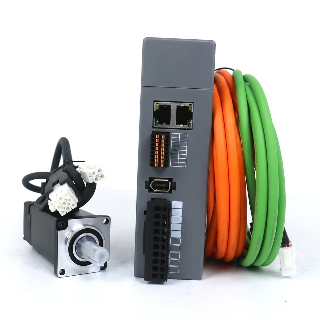
EtherCAT vs CANopen for Multi-Axis Robotic Actuation
Analyzing the real-world latency, synchronization, and cost trade-offs of EtherCAT versus CANopen in custom multi-axis servo drives.
The Hidden Costs in Custom Robot Servo OEM Manufacturing
A transparent breakdown of tooling, NRE, PCBA, and supply chain costs when scaling custom robotic joints from prototype to mass production.
The Physics of Thermal Derating in Robot Servos: Beyond the Datasheet
Why datasheet peak torque is a trap, and how thermal derating, motor constants (Km), thermal resistance (Rth), and potting define real robot performance.